Kenmore 7540 Installation Instructions - Page 1
Kenmore 7540 - Elite 36 in. Gas Manual
 |
View all Kenmore 7540 manuals
Add to My Manuals
Save this manual to your list of manuals |
Page 1 highlights
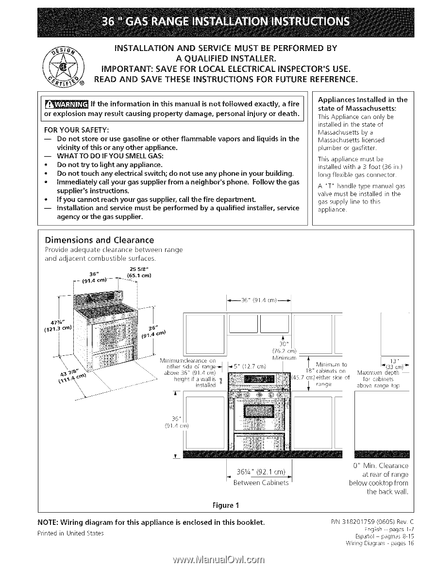
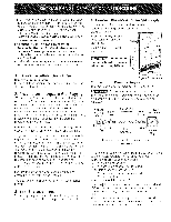
@ iNSTALLATiON AND SERVICE MUST BE PERFORMED BY A QUALiFiED iNSTALLER. iMPORTANT: SAVE FOR LOCAL ELECTRICAL iNSPECTOR'S USE. READ AND SAVE THESE iNSTRUCTiONS FOR FUTURE REFERENCE. If the information in this manual is not followed exactly, a fire or explosion may result causing property damage, personal injury or death. FOR YOUR SAFETY: -- Do not store or use gasoline or other flammable vapors and liquids in the vicinity of this or any other appliance. -- WHAT TO DO iF YOU SMELL GAS: * Do not try to light any appliance. * Do not touch any electrical switch; do not use any phone in your building. * Immediately call your gas supplier from a neighbor's phone. Follow the gas supplier's instructions. * If you cannot reach your gas supplier, call the fire department. -- Installation and service must be performed by a qualified installer, service agency or the gas supplier. Appliances Installed in the state of Massachusetts: This Appliance can only be installed in the state of Massachusetts by a Massachusetts licensed plumber or gasfitter. This appliance must be installed with a 3 foot (36 in.) long flexible gas connector. A "T" handle type manual gas valve must be installed in the gas supply line to this appliance. Dimensions and Clearance Provide adequate clearance between and adjacent combustible surfaces. 2S 5/8" 38" (65.1 cm) range 47¾" (12 ii crn) (91.4 cm)--_ Minimumclearance on either side of range_ 1_5" (12.7 cm) above 36" (91.4 cm) height if a wall is installed _ Minimum l Minimum to 18" cabinets on cm)either side of range 13" _(SS cm)_" Maximum depth for cabinets i above range top, 36 " (91.4 cm) 36¼" (92.1 cm) Between Cabinets Figure 1 NOTE: Wiring diagram for this appliance is enclosed in this booklet. Printed in United States 0" Min, Clearance at rear of range below cooktop from the back wall. P/N 318201759 (0605) Rev. C English - pages 1-7 Espaflol - paginas 8-15 Wiring Diagram - pages 16
-
 1
1 -
 2
2 -
 3
3 -
 4
4 -
 5
5 -
 6
6 -
 7
7 -
8
-
9
-
10
-
11
-
12
-
13
-
14
-
15
-
16
 |
 |