Kenmore 9031 Use and Care Guide - Page 31
P Warning
 |
View all Kenmore 9031 manuals
Add to My Manuals
Save this manual to your list of manuals |
Page 31 highlights
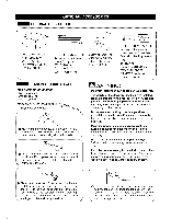
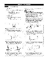
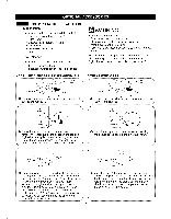
I I SIDE VENTING KIT INSTALLATION List of Parts The following parts are included with the pedestal. • Duct Outlet (A) (blower - elbow) • Duct Elbow • Duct Outlet (B) (elbow - outlet) • Cover Plate • Installation Instruction • Screw Tools Needed The following tools are needed for installation. • 1 #2 Phillips screwdriver • 1 adjusting wrench for leveling feet (included) Option 1 : side venting (Gasdryerscanonlybeventedtotheleftside.) Screw P WARNING" • Use a heavy metal vent. • Do not use plastic or thin foil duct. • Clean old ducts before installing this dryer. • Wear gloves during installation. • Failure to follow these instructions can result or fire. in death Your new dryer is shipped to vent to the rear. It can also be configured to vent to the bottom or side (right-side venting is not available on gas models). Option 2 : Bottom venting Retaining Screw Rear Exhaust Duct Rear Exhaust Duct O Remove the rear exhaust duct retaining screw. Pull out the exhaust duct. 0 Remove the rear exhaust duct retaining screw. Pull out the exhaust duct. t er Bracket Knockout 0 Press the tabs on the knockout and carefully remove the knockout for the desired vent opening (right-side venting is not available on gas models). Press the adapter duct onto the blower housing and secure to the base of the dryer as shown. ,J Knockout _tl Press the adapter duct onto the blower housing and secure to the base of the dryer as shown. f Cover Plate Cover Plate Elbow 112" (3.8 cm) Elbow O Preassemble a 4-in. (10 cm) elbow to the next 4-in. (10 cm) duct section, and secure all joints with duct tape. Be sure that the male end of the elbow faces AWAY from the dryer. Insert the elbow/duct assembly through the side opening and press it onto the adapter duct. Secure in place with duct tape. Be sure that the male end of the duct protrudes 1. in. (3.8 cm) to connect the remaining ductwork. Attach cover plate to the back of the dryer with included screw. O Insert the 4-in. (10 cm) elbow through the rear opening and press it onto the adapter duct. Be sure that the male end of the elbow faces down through hole in the bottom of the dryer. Secure in place with duct tape. Attach the cover plate to the back of the dryer with included screw. J 31 I I
-
 1
1 -
2
-
3
-
4
-
5
-
6
-
7
-
8
-
9
-
10
-
11
-
12
-
13
-
14
-
15
-
16
-
17
-
18
-
19
-
20
-
21
-
22
-
23
-
24
-
25
-
 26
26 -
 27
27 -
 28
28 -
 29
29 -
 30
30 -
 31
31 -
 32
32 -
 33
33 -
 34
34 -
 35
35 -
 36
36 -
37
-
38
-
39
-
40
-
41
-
42
-
43
-
44
-
45
-
46
-
47
-
48
-
49
-
50
-
51
-
52
-
53
-
54
-
55
-
56
-
57
-
58
-
59
-
60
-
61
-
62
-
63
-
64
 |
 |
