Kenwood 4042A Instruction Manual - Page 10
Connections
 |
UPC - 019048037244
View all Kenwood 4042A manuals
Add to My Manuals
Save this manual to your list of manuals |
Page 10 highlights
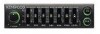
CONNECTIONS * Circled numbers indicate the procedures described on page 9. Sub-woofer Power amplifier (Optional) Left output (White)
-
 1
1 -
2
-
3
-
4
-
 5
5 -
 6
6 -
 7
7 -
 8
8 -
 9
9 -
 10
10 -
 11
11 -
 12
12 -
 13
13 -
 14
14
 |
 |

CONNECTIONS
*
Circled
numbers
indicate
the
procedures
described
on
page 9.
Sub
-woofer
Rear
speakers
Front
speakers
Power
control
supply
lead
Power
amplifier
(Optional)
Power
amplifier
(Optional)
Power
amplifier
(Optional)
NOTE
Left
output
(White)
Sub
-woofer
output
<=
1
0
=Dm --
Rig
ht
output
(Red)
Left
output
(White)
I
-13.4=2)
c
o
p
...13,2
D
22:_
Rzoutput
NTNPT1Fr
Right
output
(Red)
Left
output
(White)
<1
(
-
2)
TONPTUT
Right
output
(Red)
If
any
metal
part
of
the
RCA
cord
touches
the
vehicle
chassis,
it
will
be
a
source
of
noise.
Use
RCA
cords
as
supplied,
with
their
caps
attached.
Left
input
(White)
Cassette
receiver,
etc.
(Optional)
Zr
ar=
0;
<DZid
<=12)
Right
input
(Red)
KGC-4042A
EC
INPUT
Wiring
harness
(Accessory)
Power
control
supply
lead
Power
control
supply
lead
(Blue/Whitel
R
OONT
I
Ignition
key
Car
fuse
switch
'K)
box
O
ACC
Power
supply
lead
(Yellow)
0
(To
battery)
Car
fuse
box
(Main
fuse)
Ground
lead
(Black)
0
(To
vehicle
chassis)
n
G
0
Battery
`4
01
"\\
•
To
prevent
fires
when
the
power
supply
(yellow)
leads
are
short-
circuited
by
coming
into
contact
with
the
vehicle
chassis
(ground),
only
connect
the
power
supply
after
making
the
fuse
box
connections
first.
AWARNING
NOTE
tl
TP
screw
(M3x6)
(Accessory)
10
Installation
•
When
an
optional
RCA
extension
cord
is
used
as
a
ground
wire,
attach
it
to
the
back
of
the
unit
using
the
TP
screw
(M3x6)
supplied
with
it.