Kenwood KAC-5201 Instruction Manual - Page 2
System examples, Power indicator, Controls, Connection - amplifier
 |
View all Kenwood KAC-5201 manuals
Add to My Manuals
Save this manual to your list of manuals |
Page 2 highlights
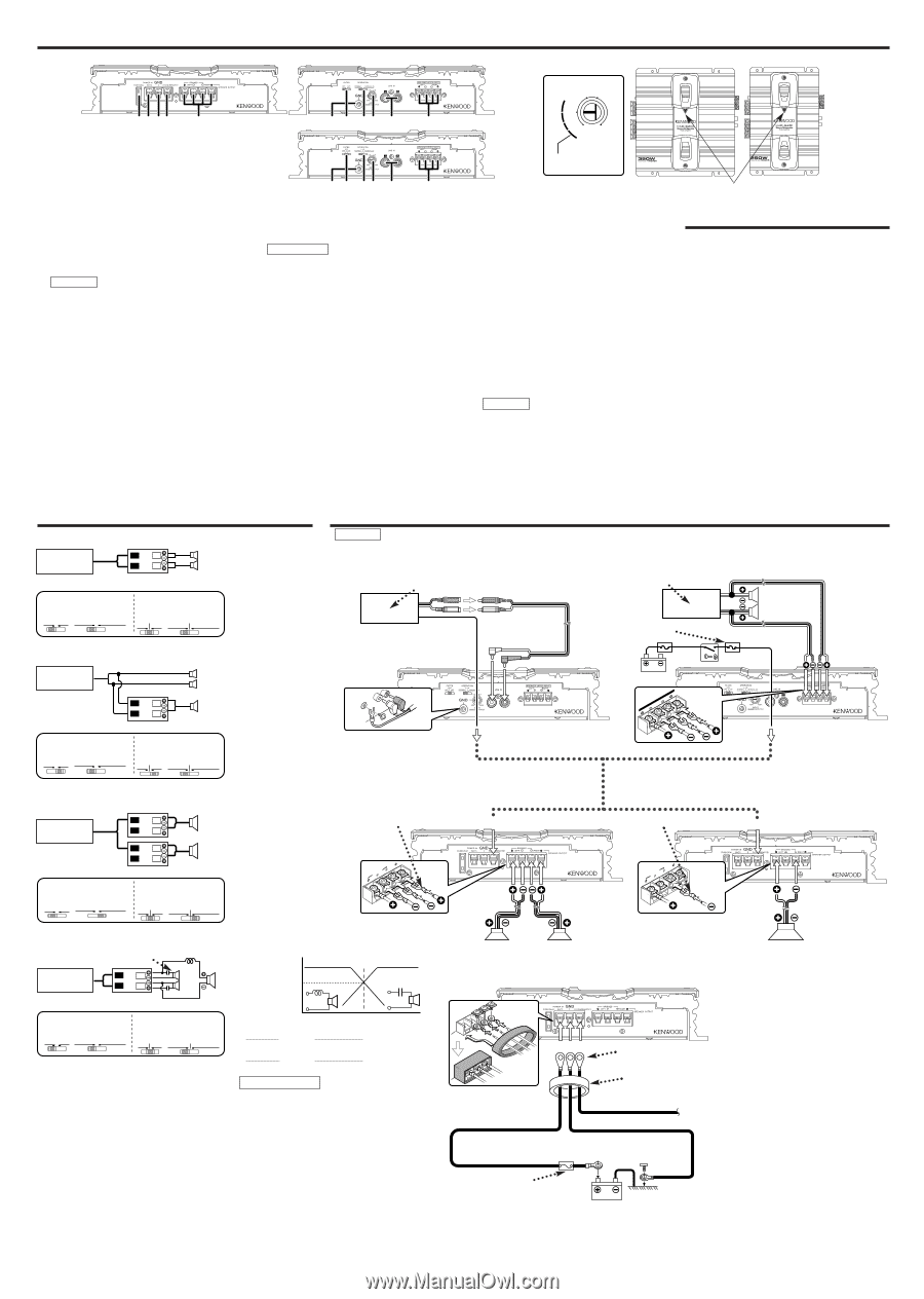
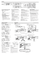
Controls 25 25 25 25 KAC-5201 KCA-6201 1 234 5 6 7 89 0 ! 6 7 89 0 ! KAC-5201 KAC-6201 9 0.5 0.3 10 1.0 15 20 MIN MAX (W) INPUT SENSITIVITY(V) 25W or greater KAC-6201 KAC-5201 Power indicator Operations of the following control and switches are required in accordance with the center unit and speakers connected with this unit. 1 Fuse 25 A × 1 : KAC-6201 15 A × 1 : KAC-5201 NOTE If you can't find the specified capacity fuse at your store etc., consult your Kenwood dealer. 2 Battery terminal 3 Ground terminal 4 Power control (REMOTE) terminal 5 SPEAKER OUTPUT terminals • Stereo Connections: When you wish to use the unit as a stereo amplifier, stereo connections are used. • Bridged Connections: When you wish to use the unit as a high-output monaural amplifier, bridged connections are used. (Make connections to the LEFT channel (+) and the RIGHT channel (-) SPEAKER OUTPUT terminals.) 6 RCA cable ground lead terminal When using an RCA cable with a ground lead attached, connect the ground lead to this terminal. 2CAUTION Do not use this terminal for power source grounding. This unit will be damaged if the power source grounding wire is connected to this terminal. 7 FILTER switch These switches allow filtering of the speaker output signals. • HPF (High Pass Filter) position (KAC6201 only) Only frequencies of 150 Hz or higher are output. (Frequencies below 150 Hz are cut.) • LPF (Low Pass Filter) position Only frequencies of 80 Hz or lower are output. (Frequencies above 80 Hz are cut.) The Lch and Rch will be mixed before output even if the operation switch is set to STEREO. • OFF position The original sound without filtering is output. 8 OPERATION switch This switch allows selection of the amplification method of input signals. • STEREO position The amplifier can be used as a stereo amplifier. • L+R position (KAC-6201 only) The input left and right signals are combined before being amplified. Use this position when the unit is used for subwoofer speakers or the L+R (monaural) sound is required. • MONO (Lch) position Amplifies the signal input from the left side only. Set to this position and make bridged connections to use as a high-power monaural amplifier. (The input right signal is not output.) 9 INPUT SENSITIVITY control Set this control according to the pre-output level of the center unit connected with this unit, or to the maximum power output of the genuine-accessory car stereo. Use the diagram on the right as a guide. NOTE For the pre-output level or the maximum power output, refer to the "Specifications" in the instruction manual of the center unit. 0 LINE IN terminal ! Speaker level input terminals Power indicator When the power is turned on, the Power indicator lights. If the Power indicator does not light when the power is turned on, the protection function may be activated. Check whether there is any indication of trouble. ■ The protection function is activated in the following situations: This unit is equipped with a protection function for protecting this unit and your speakers from various accidents or problems that can occur. When the protection function is triggered, the Power indicator goes off and the amplifier stops operating. • When a speaker wire may be short-circuited. • When a speaker output contacts ground. • When the unit malfunctions and a DC signal is sent to the speaker output. • When the internal temperature is high and unit won't operate. • When a ground wire of the center unit (cassette receiver, CD receiver, etc.) or this unit is not connected to a metal part serving as an electrical ground passing electricity to the battery's negative - terminal. System examples ■ 2-channel system CENTER UNIT L L R R Left speaker Right speaker KAC-5201 7 8 FILTER OPERATION OFF LPF STEREO MONO(Lch) KAC-6201 7 8 FILTER OPERATION OFF L+R HPF LPF STEREO MONO(Lch) ■ Subwoofer system CENTER UNIT L L R R Left speaker Right speaker Subwoofer KAC-5201 7 8 FILTER OPERATION OFF LPF STEREO MONO(Lch) KAC-6201 7 8 FILTER OPERATION OFF L+R HPF LPF STEREO MONO(Lch) ■ 1-channel system CENTER UNIT L L L R R R L L R R Left speaker Right speaker KAC-5201 7 8 FILTER OPERATION OFF LPF STEREO MONO(Lch) KAC-6201 7 8 FILTER OPERATION OFF L+R HPF LPF STEREO MONO(Lch) Connection *Commercially available parts NOTE For safe installation, read "Installation procedure" before starting work. ■ RCA cable connection ■ Speaker level input connection CENTER UNIT (Cassette receiver, CD receiver, etc.) Genuine-accessory car stereo (No line output center unit etc.) Speaker RCA cable* Car fuse box 6 GND Battery ! LEVEL RINIGHPTUT SPELEAFKT ER ACC Power control wire* ■ Speaker stereo connection Lead terminal* 4 5BRIDGED LEFT RIGHT ■ Speaker bridge connection Lead terminal* 4 5BRIDGED LEFT RIGHT ■ Tri-mode CENTER UNIT High pass L L R R L Crossover Frequency C 0 dB Subwoofer (L + R) -3 dB C L C KAC-5201 7 8 FILTER OPERATION OFF LPF STEREO MONO(Lch) KAC-6201 7 8 FILTER OPERATION OFF L+R HPF LPF STEREO MONO(Lch) Principle of Tri-mode Method of frequency band division using a coil and capacitor ... in case of 6dB/oct. slope Coil (L): Passes low frequencies and blocks high frequencies. (Low pass) Capacitor (C): Passes high frequencies and blocks low frequencies. (High pass) Example: When it is required to set a crossover frequency of 120 Hz using speakers with an impedance of 4 ohms. fc=Cut of Frequency (Hz) R=Speaker Impedance (Ω) Frequency C= 159000 fc x R (µF) = 159000 120Hz x 4Ω = 331.25 µF L= 159 x R fc (mH) = 159 x 4Ω 120Hz = 5.3 mH 2CAUTION • If you wish to bridge-connect a speaker, the speaker impedance must be no less than 4 ohms. Connecting a speaker with an impedance lower than 4 ohms may damage the unit. • Be sure to connect capacitors to speakers to which high frequencies will be passed. Failure to do so will result in a drop of the combined impedance with the subwoofer. • Ensure that the withstand voltage and current ratings of the capacitors (C) and coils (L) are sufficient. Left speaker Right speaker ■ Power wire connection 234 Lead terminal* Terminal cover Battery wire* Power control wire* Ground wire* Protective Fuse* Battery Subwoofer
-
 1
1 -
 2
2
 |
 |