Kenwood KAC-6202 Instruction Manual - Page 4
Controls / Indicator - diagram
 |
View all Kenwood KAC-6202 manuals
Add to My Manuals
Save this manual to your list of manuals |
Page 4 highlights
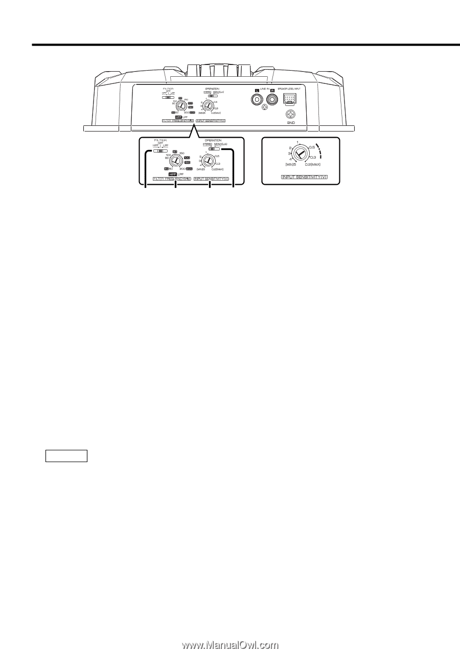
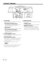
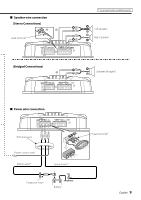
Controls / Indicator 3 40 30 20 10 (W) 12 34 1 FILTER switch This switch allows to apply high-pass or low-pass filtering to the speaker outputs. • HPF (High-Pass Filter) position: The filter outputs the band of higher frequencies than the frequency set with the FILTER FREQUENCY control. • OFF position: The entire bandwidth is output without filtering. • LPF (Low-Pass Filter) position: The filter outputs the band of lower frequencies than the frequency set with the FILTER FREQUENCY control. 2 FILTER FREQUENCY control Sets the cutoff frequency when the FILTER switch is set to LPF or HPF. 3 INPUT SENSITIVITY control Set this control according to the pre-output level of the center unit connected with this unit, or to the maximum power output of the genuineaccessory car stereo. Use the diagram on the right as a guide. NOTE For the pre-output level or the maximum power output, refer to the in the instruction manual of the center unit. 4 OPERATION switch This switch is used to select the operation mode of the amplifier. • STEREO position: The amplifier can be used as a stereo amplifier. • MONO (Lch) position: Amplifies the signal input from the left side only. Set to this position and make bridged connections to use as a high-power monaural amplifier. (The input right signal is not output.) 4 English
-
 1
1 -
 2
2 -
 3
3 -
 4
4 -
 5
5 -
 6
6 -
 7
7 -
 8
8 -
 9
9 -
 10
10 -
11
-
12
-
13
-
14
 |
 |