Kenwood KAC959 Instruction Manual - Page 2
Power indicator, Connection - 5 channel amplifier
 |
UPC - 019048127198
View all Kenwood KAC959 manuals
Add to My Manuals
Save this manual to your list of manuals |
Page 2 highlights
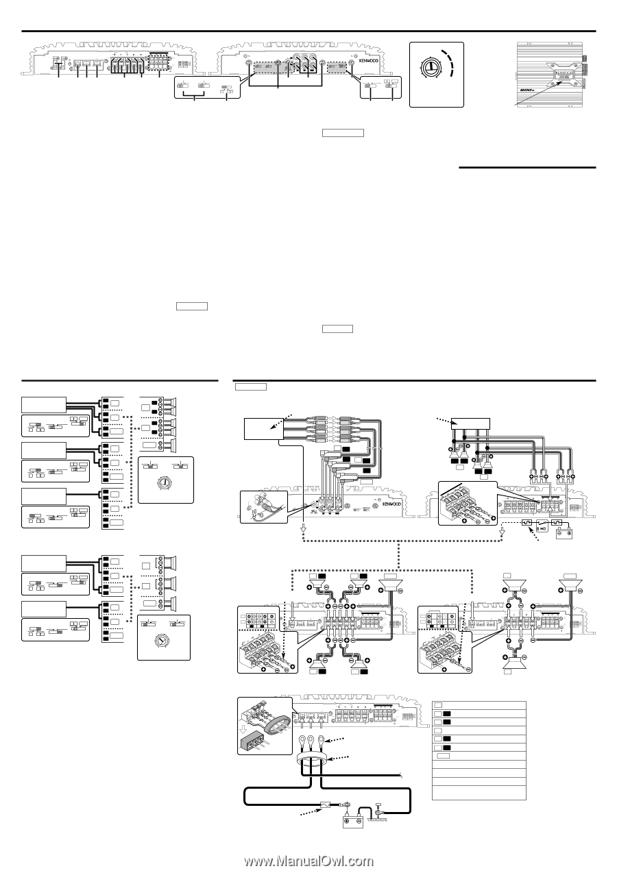
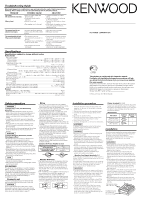
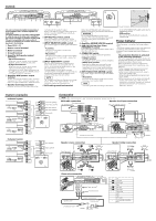
Controls 25 25 FUSE(25Ax2) 1 P.CON POWER IN GND BATT SPEAKER OUTPUT A BRIDGED LEFT RIGHT SUB B SUB SPEAKER LEVEL INPUT LEFT RIGHT A SPEAKER LEVEL INPUT A B B L R 23 4 56 7 150Hz 80Hz OFF 150Hz 80Hz OFF GND 1 1 L 2 0.5 2 0.5 3 4 0.3 150Hz 80Hz OFF 150Hz 3 80Hz OFF 4 0.3 R (MIN)5 0.2(MAX) (MIN)5 0.2(MAX) A.CH INPUT A.CH HPF B.CH HPF B.CH INPUT SENSITIVITY(V) SENSITIVITY(V) A A B A INPUT SELECTOR B LINE IN SUB 1 2 0.5 100 80 3 4 0.3 OPERATION STEREO MONO(Lch) AB 70 SUB (MIN)5 0.2(MAX) 50 150 170 200 SUB.CH INPUT SENSITIVITY(V) SUB.CH LPF FREQUENCY(Hz) INPUT SELECTOR 5/4/3 CHANNEL POWER AMPLIFIER !@ # OPERATION STEREO MONO(Lch) A B SUB A.CH HPF B.CH HPF A AB INPUT SELECTOR 8 9 0 INPUT SELECTOR $ % 0 40 1 25 2 0.5 15 3 4 0.3 10 (MIN)5 0.2(MAX) (W) INPUT SENSITIVITY(V) Power indicator MAXIMUM POWER The unit is a 5-channel amplifier incorporating 2 stereo amplifiers and 1 monaural amplifier in a single body. The stereo amplifier on one side is called amplifier A, while the one on the other side is amplifier B. The monaural amplifier is called the amplifier SUB. This unit is compatible with a large variety of systems by combining the switches and functions described in the following. 1 Fuse (25 A ´ 2) 2 Power control terminal 3 Battery terminal 4 Ground terminal 5 Amplifier A/B speaker output terminals • Stereo Connections: When you wish to use the unit as a stereo amplifier, stereo connections are used. • Bridged Connections: When you wish to use the unit as a highoutput monaural amplifier, bridged connections are used. (Make connections to the LEFT channel (+) and the RIGHT channel (-) SPEAKER OUTPUT terminals.) 6 Amplifier SUB speaker output terminal As this unit accepts speakers with a minimum impedance of 2 ohms, connect speakers with 2-ohm or higher impedance to these terminals. 7 Speaker level input terminals A center unit with no RCA output can still be connected to the speaker output. Again, even without a power control signal, the power is switched ON/OFF automatically by the speaker signal. 8 HPF(High-Pass Filter) switch When this switch is set to 80 Hz or 150 Hz, frequencies below the setting value will be cut. 9 INPUT SELECTOR (A/AB) switch This switch toggles the input signal of amplifier B. • A position: The input for terminal A is output from amplifiers A and B. • AB position: The input for terminal A is output from amplifier A, while the input for terminal B is output from amplifier B. 0 INPUT SENSITIVITY control Set this control according to the pre-output level of the center unit connected with this unit, or to the maximum power output of the genuine-accessory car stereo. Use the diagram on the right as a guide. The sensitivities of amplifiers A, B and SUB can be adjusted independently regardless of the position of the input selector switch. NOTE For the pre-output level or the maximum power output, refer to the "Specifications" in the instruction manual of the center unit. ! RCA cable ground lead terminal When using an RCA cable with a ground lead attached, connect the ground lead to this terminal. 2CAUTION Do not use this terminal for power source grounding. This unit will be damaged if the power source grounding wire is connected to this terminal. @ Amplifier A/B/SUB LINE IN terminal # SUB.CH LPF(Low-Pass Filter) FREQUENCY control This control adjusts the frequency band output from this SUB channel. $ OPERATION switch This switch is used to select the operation mode of the amplifier. • STEREO position: The amplifier can be used as a stereo amplifier. • MONO (Lch) position: Amplifies the signal input from the left side only. Set to this position and make bridged connections to use as a high-power monaural amplifier. (The input right signal is not output.) % INPUT SELECTOR (AB/SUB) switch This switch toggles the input signal of amplifier SUB. • AB position: The input for terminals A and B input is mixed and output from amplifier SUB. NOTE The input signal varies according to the setting of the INPUT SELECTOR (A/AB) switch and the OPERATION switch. • SUB position: The input for the SUB terminal is output by amplifier SUB. Power indicator When the power is turned on, the Power indicator lights. If the Power indicator does not light when the power is turned on, the protection function may be activated. Check whether there is any indication of trouble. s The protection function is activated in the following situations: This unit is equipped with a protection function for protecting this unit and your speakers from various accidents or problems that can occur. When the protection function is triggered, the Power indicator goes off and the amplifier stops operating. • When a speaker wire may be short-circuited. • When a speaker output contacts ground. • When the unit malfunctions and a DC signal is sent to the speaker output. • When the internal temperature is high and unit won't operate. • When a ground wire of the center unit (cassette receiver, CD receiver, etc.) or this unit is not connected to a metal part serving as an electrical ground passing electricity to the battery's negative - terminal. System examples s 5-channel system F CENTER UNIT 9 OPERATION A B SUB STEREO MONO(Lch) R $ A A B INPUT SELECTOR INPUT % SELECTOR N-F CENTER F UNIT 9 OPERATION A B SUB STEREO MONO(Lch) R $ A A B INPUT SELECTOR INPUT % SELECTOR LA R L RB L SUB R LA R L RB L SUB R CENTER UNIT 9 OPERATION A B SUB STEREO MONO(Lch) $ A A B INPUT SELECTOR INPUT % SELECTOR LA R L RB L SUB R s 3-channel system L CENTER UNIT 9 OPERATION A B SUB R STEREO MONO(Lch) $ A A B INPUT SELECTOR INPUT % SELECTOR N-F L CENTER UNIT 9 OPERATION A B SUB R STEREO MONO(Lch) $ A A B INPUT SELECTOR INPUT % SELECTOR LA R L RB L SUB R LA R L RB L SUB R Connection L A R L B R Front left speaker Front right speaker NOTE For safe installation, read "Installation procedure" before starting work. s RCA cable connection CENTER UNIT (Cassette receiver, CD receiver, etc.) s Speaker level input connection Genuine-accessory car stereo (No line output center unit etc.) Rear left speaker Rear right speaker SUB Subwoofer AL 150Hz 150Hz 8 80Hz OFF 80Hz OFF A.ch HPF 100 80 70 B.ch HPF 150 170 50 200 # SUB.CH LPF FREQUENCY(Hz) ! GND R BL R SUB RCA cable* GND 1 2 0.5 1 L 2 0.5 3 4 0.3 150Hz 80Hz OFF 150Hz 3 80Hz OFF 4 0.3 R (MIN)5 0.2(MAX) (MIN)5 0.2(MAX) A.CH INPUT A.CH HPF B.CH HPF B.CH INPUT SENSITIVITY(V) SENSITIVITY(V) A A B A INPUT SELECTOR B LINE IN SUB 1 2 0.5 100 80 3 4 0.3 OPERATION STEREO MONO(Lch) AB 70 SUB (MIN)5 0.2(MAX) 50 150 170 200 SUB.CH INPUT SENSITIVITY(V) SUB.CH LPF FREQUENCY(Hz) INPUT SELECTOR 5/4/3 CHANNEL POWER AMPLIFIER LR A LR B 25 7 LEVEL RINIGHPTUT SPELEAFKT ER FUSE(25Ax2) 25 P.CON POWER IN BATT GND SPEAKER OUTPUT A BRIDGED LEFT RIGHT SUB B SUB SPEAKER LEVEL INPUT LEFT RIGHT A SPEAKER LEVEL INPUT A B B L R Power control wire* ACC Battery Car fuse box BRIDGED BRIDGED A Left speaker B Right speaker SUB Subwoofer 150Hz 150Hz 8 80Hz OFF 80Hz OFF A.ch HPF 100 80 70 B.ch HPF 150 170 50 200 # SUB.CH LPF FREQUENCY(Hz) s Speaker stereo connection AL AR SUB Lead terminal* 2 BRIDGED A B L 25 FUSE(25Ax2) R SUB 25 5 SUB RIGHT BRIDGED LEFT 6 P.CON POWER IN BATT GND SPEAKER OUTPUT A BRIDGED LEFT RIGHT SUB B SUB SPEAKER LEVEL INPUT LEFT RIGHT A SPEAKER LEVEL INPUT A B B L R s Speaker bridge connection A Bridge SUB Lead terminal* 2 BRIDGED A B L 25 FUSE(25Ax2) R SUB 25 5 SUB RIGHT BRIDGED LEFT 6 P.CON POWER IN BATT GND SPEAKER OUTPUT A BRIDGED LEFT RIGHT SUB B SUB SPEAKER LEVEL INPUT LEFT RIGHT A SPEAKER LEVEL INPUT A B B L R BL BR s Power wire connection 25 FUSE(25Ax2) 25 P.CON POWER IN BATT GND SPEAKER OUTPUT A BRIDGED LEFT RIGHT SUB B SUB SPEAKER LEVEL INPUT LEFT RIGHT A SPEAKER LEVEL INPUT A B B L R 23 4 Lead terminal* Terminal cover Battery wire* Power control wire* Ground wire* B Bridge Description of markings in the figure. A /L AL AR B /R BL BR SUB F R N-F * Left Front left Front right Right Rear left Rear right Subwoofer Front Rear Non-fader Commercially available parts Protective Fuse* Battery
-
 1
1 -
 2
2
 |
 |