Kenwood KMR-M332BT Quick Start Guide - Page 9
Part list supplied
 |
View all Kenwood KMR-M332BT manuals
Add to My Manuals
Save this manual to your list of manuals |
Page 9 highlights
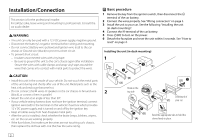
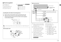
Part list (supplied) (A) Faceplate (×1) (B) Trim plate (×1) (C) Mounting sleeve (×1) (D) Wiring harness (×1) (E) Extraction key (×2) (F) Screws (supplied for / ) M5 × 7 mm (×4) M5 × 6 mm (×4) M4 × 8 mm (×1) Installing the unit (without mounting sleeve) 1 Remove the mounting sleeve and trim plate from the unit. 2 Align the holes in the unit (on both sides) with the vehicle mounting bracket and secure the unit with screws (supplied/ commercially available). Use only the specified screws. Using wrong screws might damage the unit. Removing the unit Wiring connection Fuse (10 A) Antenna terminal If no connections are made, do not let the wire come out from the tab. Car fuse box Ignition switch Car fuse box Battery a Brown: Connect to the device equipped with muting feature to mute this unit b Blue/white: To the power control terminal when using the optional power amplifier or to the antenna control terminal in the vehicle c Light blue/yellow: To the steering wheel remote control adapter or to KENWOOD Marine Remote Control unit (optional accessory) for d Red: Ignition 12 V e Yellow: Battery 12 V f Black: Ground g White ª, White/black ·: Front speaker (left) h Gray ª, Gray/black ·: Front speaker (right) i Green ª, Green/black ·: Rear speaker (left) j Purple ª, Purple/black ·: Rear speaker (right) 3
-
 1
1 -
2
-
3
-
 4
4 -
 5
5 -
 6
6 -
 7
7 -
 8
8 -
 9
9 -
 10
10 -
 11
11 -
 12
12 -
 13
13 -
 14
14 -
15
-
16
-
17
-
18
-
19
-
20
-
21
-
22
-
23
-
24
-
25
-
26
-
27
-
28
-
29
-
30
-
31
-
32
 |
 |
