Kenwood KRC-21SA User Manual - Page 12
Connecting Wires to Terminals, Connector Function Guide
 |
View all Kenwood KRC-21SA manuals
Add to My Manuals
Save this manual to your list of manuals |
Page 12 highlights
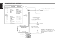
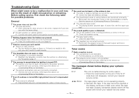
Connecting Wires to Terminals English Connector Function Guide Pin Numbers for ISO Connectors Cable Color External Power Connector A-4 Yellow A-5 Blue/White A-7 Red A-8 Black Functions Battery Power Control Ignition (ACC) Earth (Ground) Connection Speaker Connector B-1 B-2 B-3 B-4 B-5 B-6 B-7 B-8 Purple Purple/Black Gray Gray/Black White White/Black Green Green/Black Rear Right (+) Rear Right (-) Front Right (+) Front Right (-) Front Left (+) Front Left (-) Rear Left (+) Rear Left (-) Fuse (10A) 13 Wiring harness (Accessory1) 16 Antenna Conversion Adaptor (ISO-JASO) (Accessory3) 2 Antenna Cord (ISO) 1 FM/AM antenna input 3 Do not let the wire come out from the tab. TEL MUTE Not Used Battery wire (Yellow) 6 Ignition wire (Red) 7 If no connections are made, do not let the wire come out from the tab. 18 A-7 Pin (Red) 8 A-4 Pin (Yellow) 9 Connector A Connector B 864 2 75 31 8 64 2 75 31 ANT CONT Depending on what antenna you are using, connect either to the control terminal of the motor antenna, or to the power terminal for the booster amplifier of the film-type antenna. Motor antenna control wire (Blue) - 12 -
-
 1
1 -
2
-
3
-
4
-
5
-
6
-
 7
7 -
 8
8 -
 9
9 -
 10
10 -
 11
11 -
 12
12 -
 13
13 -
 14
14 -
 15
15 -
 16
16 -
 17
17 -
18
-
19
-
20
-
21
-
22
-
23
-
24
-
25
-
26
-
27
-
28
-
29
-
30
-
31
-
32
-
33
-
34
-
35
-
36
-
37
-
38
-
39
-
40
-
41
-
42
-
43
-
44
-
45
-
46
-
47
-
48
 |
 |
