Kenwood KVT-54DVDR User Manual 1 - Page 3
Connecting Wires to Terminals
 |
View all Kenwood KVT-54DVDR manuals
Add to My Manuals
Save this manual to your list of manuals |
Page 3 highlights
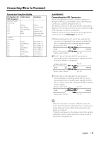
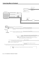
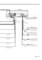
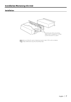
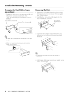
Connecting Wires to Terminals Connector Function Guide Pin Numbers for ISO Connectors External Power Connector A-4 A-5 A-6 A-7 A-8 Cable Colour Yellow Blue/White Orange/White Red Black Speaker Connector B-1 B-2 B-3 B-4 B-5 B-6 B-7 B-8 Purple Purple/Black Gray Gray/Black White White/Black Green Green/Black Functions Battery Power Control Dimmer Ignition (ACC) Earth (Ground) Connection Rear Right (+) Rear Right (-) Front Right (+) Front Right (-) Front Left (+) Front Left (-) Rear Left (+) Rear Left (-) 2WARNING Connecting the ISO Connector The pin arrangement for the ISO connectors depends on the type of vehicle you drive. Make sure to make the proper connections to prevent damage to the unit. The default connection for the wiring harness is described in 1 below. If the ISO connector pins are set as described in 2 or 3, make the connection as illustrated. Please be sure to reconnect the cable as shown 2 below to install this unit to the Volkswagen vehicles etc. 1(Default setting) The A-7 pin of the vehicle's ISO connector is linked with the ignition, and the A-4 pin is connected to the constant power supply. Ignition cable (Red) A-7 Pin Unit Vehicle Battery cable (Yellow) A-4 Pin 2The A-7 pin of the vehicle's ISO connector is connected to the constant power supply, and the A-4 pin is linked to the ignition. Ignition cable (Red) Unit A-7 Pin Vehicle Battery cable (Yellow) A-4 Pin 3The A-4 pin of the vehicle's ISO connector is not connected to anything, while the A-7 pin is connected to the constant power supply (or both the A-7 and A-4 pins are connected to the constant power supply). Ignition cable (Red) A-7 Pin Unit Vehicle Battery cable (Yellow) A-4 Pin ⁄ • When the connection is made as in 3 above, the unit's power will not be linked to the ignition key. For that reason, always make sure to turn off the unit's power when the ignition is turned off. To link the unit's power to the ignition, connect the ignition cable (ACC...red) to a power source that can be turned on and off with the ignition key. English | 3
-
 1
1 -
 2
2 -
 3
3 -
 4
4 -
 5
5 -
 6
6 -
 7
7 -
 8
8
 |
 |
