Kenwood KVT-817DVD Installation Manual - Page 4
Connection - kvt
 |
UPC - 019048162557
View all Kenwood KVT-817DVD manuals
Add to My Manuals
Save this manual to your list of manuals |
Page 4 highlights
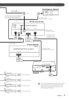
Connection When handling an optical cable for wiring, use care not to exceed the minimum cable bend radius of 30 mm. If you exceed the minimum bend limit, optical fibers within the optical cable may be damaged. 30R Optical output (KVT-817DVD only) Monitor unit An Optical cable (Accessory 3) is fixed with a chassis using harness band (Accessory ^). (KVT-817DVD only) For the sake of safety, be sure to connect the parking sensor. Connect to the vehicle's parking brake detection switch harness using the supplied relay connector. (Black) Parking sensor wire (Green) PRK SW Accessory 4 To vehicle's reverse lamp harness Reverse sensor wire (Pink) REVERSE Car fuse box (Main fuse) + Battery To car light control switch To Steering remote Dimmer control wire (Orange/White) ILLUMI Steering remote control input (Light Blue/Yellow) REMO.CONT Ignition key switch ACC A B Car fuse box C Ignition wire (Red) A Battery wire (Yellow) B ACC (5A) BATT C Ground wire (Black) - (To car chassis) Receiver unit (front side) FM/AM antenna input FM /AM ANTENNA AV INPUT 2 VIDEO L AV INPUT 1 VIDEO L AV OUTPUT R L R-CAM V-IN CENTER SUB R R VIDEO [MONO] PRE OUTPUT REAR L FRONT L R R POWER Antenna Cord Accessory 5 To Subwoofer system Accessory % (KVT-817DVD only) C Accessory 1 Ground wire (Black) - (To car chassis) Battery wire (Yellow) B (10A) Connect to the terminal that is grounded when either the Mute wire (Brown) telephone rings or during conversation. MUTE To connect the Kenwood navigation system, consult your navigation manual. Depending on what antenna you are using, connect either to the Motor antenna control wire (Blue) control terminal of the motor antenna, or to the power terminal for the booster amplifier of the film-type antenna. ANT CONT When using the optional power amplifier, connect to its power Power control wire (Blue/White) control terminal. P. CONT To "EXT.AMP.CONT." terminal of the amplifier having the external External amplifier control wire (Pink/Black) amp control function. EXT.CONT 4 | English
-
 1
1 -
 2
2 -
 3
3 -
 4
4 -
 5
5 -
 6
6 -
 7
7 -
 8
8 -
 9
9 -
 10
10 -
11
-
12
-
13
-
14
-
15
-
16
-
17
-
18
-
19
-
20
-
21
-
22
-
23
-
24
-
25
-
26
-
27
-
28
-
29
-
30
-
31
-
32
-
33
-
34
-
35
-
36
-
37
-
38
-
39
-
40
-
41
-
42
-
43
-
44
 |
 |
