Kenwood XXV-03A User Manual - Page 5
Controls
 |
View all Kenwood XXV-03A manuals
Add to My Manuals
Save this manual to your list of manuals |
Page 5 highlights
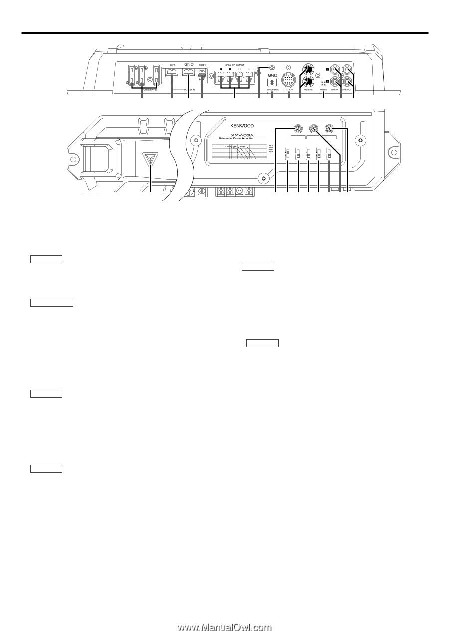
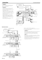
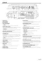
Controls 78 25 25 25 1 2 34 456 23 9 01 5 6 7 89 0 !@ 1 150 100 2 0.5 3 70 4 (MIN)5 0.2(MAX) 50 200 INPUT LPF SENSITIVITY(V) FREQUENCY(Hz) 40 200 B.R.F FREQUENCY(Hz) LPF OPERATION 0 200 Hz AMP CONT PHASE BRF ISF ISF FREQUENCY -4 150 Hz ON 180˃ -12dB ON 25Hz 100 Hz -8 70 Hz -12 50 Hz -6dB -16 -20 30 40 50 60 100 200 300 400 1K (Hz) OFF 0˃ OFF OFF 15Hz # 1 Fuse (25 A × 3) 2 Battery terminal 3 Ground terminal 4 Power control terminal Controls the unit ON/OFF. NOTE Controls the unit power. Be sure to connect it with all the systems. 5 Speaker output terminals As this unit accepts speakers with a minimum impedance of 1 ohm, connect speakers with 1-ohm or higher impedance to these terminals. 2CAUTION The rated input of the speakers should be no less than the maximum output of the amplifier. Otherwise malfunction may result. 6 RCA cable ground lead terminal When using an RCA cable with a ground lead attached, connect the ground lead to this terminal. 7 ID NUMBER switch Sets an amp identification number (ID) to be used for amplifier control from the Center Unit. Assign ID Number "0" to an amplifier when you use it as the Master amplifier. Assign ID Numbers "1" to "7" to amplifiers when you use them as Slave amplifiers. Do not duplicate these numbers. NOTE After you have changed ID numbers of amplifiers, turn Off the POWER switch of the Center Unit and turn it On again. 8 TO H/U terminal After you have set the Master amplifier, connect it to the Center Unit. 9 REMOTE terminals Used to connect to Slave amplifiers. 0 RESET button Resets the microprocessor of the unit. NOTE The values you have set with the Amplifier Control are NOT reset. ! LINE IN terminal @ LINE OUT terminal The signal that's input from the line input terminal is output. 1 # Power indicator Lights when the POWER switch is turned On. The indicator flashes several seconds when the POWER switch is turned On or when the Protection function is activated. $ INPUT SENSITIVITY control Set this control according to the pre-output level of the center unit connected with this unit. NOTE For the pre-output level, refer to the in the instruction manual of the center unit. % AMP CONT (amplifier control) switch Used to bypass the circuit when you do not control the sound with the Amplifier Control. • ON position: Allows you to control the sound with the Amplifier Control. • OFF position: Bypasses the Amplifier Control circuit. NOTE Amplifier control is possible even while OFF. ^ PHASE switch When this switch is set "180°" (Reverse) the speaker output phase is reversed. & BRF (band reject filter) switch When this switch is set to "-6dB"/"-12dB", frequencies in the band set with the "B.R.F. FREQUENCY" control are rejected and eliminated. The band rejection allows to reduce resonance inside the vehicle compartment and standing waves. (page 8) * ISF (infrasonic filter) switch When this switch is set to "ON", the inaudible, ultralow frequencies below the frequency set with the "ISF FREQUENCY" switch are cut off. This improves the reproduction performance of the speakers by eliminating unnecessary oscillations which will not become sound. ( ISF FREQUENCY switch Switches the cutoff frequency when the "ISF" switch is set to "ON". ) LPF(Low-Pass Filter) FREQUENCY control This control adjusts the frequency band output from this unit. @1 B.R.F. FREQUENCY control Sets the rejection frequency when the "BRF" switch is set to "-6dB"/"-12dB". (page 8) English 5
-
 1
1 -
 2
2 -
 3
3 -
 4
4 -
 5
5 -
 6
6 -
 7
7 -
 8
8 -
 9
9 -
 10
10 -
 11
11 -
12
-
13
-
14
-
15
-
16
-
17
-
18
-
19
-
20
-
21
-
22
-
23
-
24
-
25
-
26
-
27
-
28
 |
 |