KitchenAid KBFS20EVMS Use & Care Guide - Page 5
Refrigerator Doors and Drawer - 5 parts
 |
UPC - 883049141596
View all KitchenAid KBFS20EVMS manuals
Add to My Manuals
Save this manual to your list of manuals |
Page 5 highlights
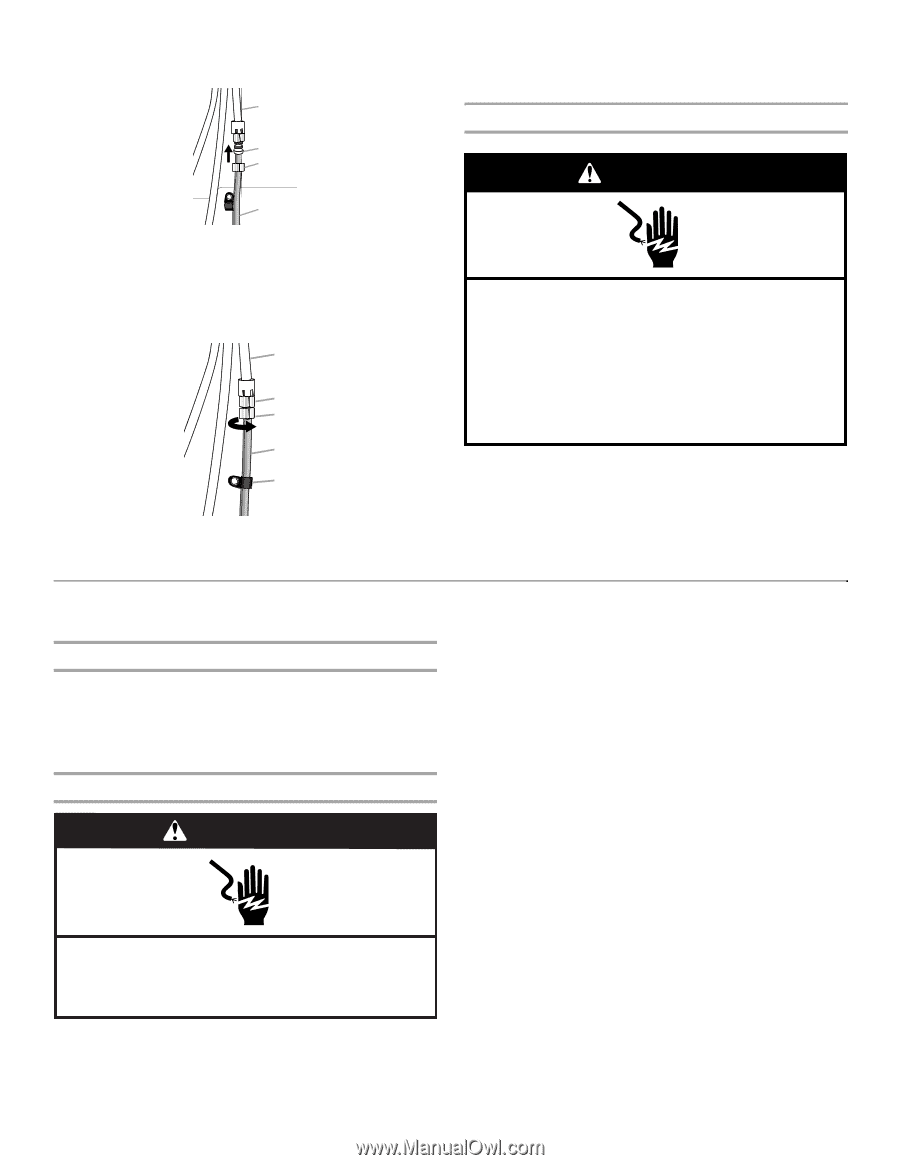
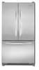
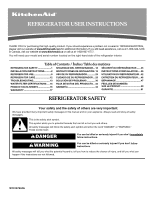
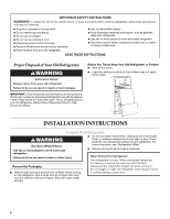
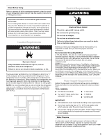
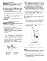
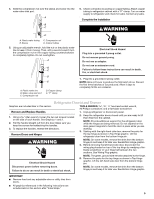
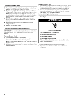
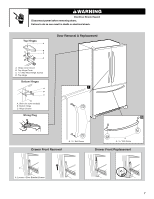
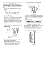
4. Slide the compression nut over the sleeve and screw into the water valve inlet port. A B C D A. Plastic water tubing C. Compression nut B. Sleeve D. Copper tubing 5. Using an adjustable wrench, hold the nut on the plastic water line to keep it from moving. Then, with a second wrench turn the compression nut on the copper tubing counterclockwise to completely tighten. Do not overtighten. A B C D E A. Plastic water line B. Water valve inlet port C. Compression nut D. Copper tubing E. "P" clamp 6. Check connection by pulling on copper tubing. Attach copper tubing to refrigerator cabinet with a "P" clamp. Turn on water supply to refrigerator and check for leaks. Correct any leaks. Complete the Installation WARNING Electrical Shock Hazard Plug into a grounded 3 prong outlet. Do not remove ground prong. Do not use an adapter. Do not use an extension cord. Failure to follow these instructions can result in death, fire, or electrical shock. 1. Plug into a grounded 3 prong outlet. NOTE: Allow 24 hours to produce the first batch of ice. Discard the first three batches of ice produced. Allow 3 days to completely fill the ice container. Refrigerator Door(s) and Drawer Graphics are included later in this section. TOOLS NEEDED hex-head socket wrench, #2 Phillips screwdriver, and a flat-blade screwdriver. Remove and Replace Handles 1. Unplug refrigerator or disconnect power. 1. Using a Allen wrench, loosen the two set screws located on the side of each handle. See Graphics 1 and 2. 2. Pull the handle straight out from the door. Make sure you keep the screws for reattaching the handles. 3. To replace the handles, reverse the directions. Remove Doors and Hinges 2. Keep the refrigerator doors closed until you are ready to lift them free from the cabinet. NOTE: Provide additional support for the refrigerator door while the hinges are being removed. Do not depend on the door gasket magnets to hold the door in place while you are working. 3. Starting with the right-hand side door, remove the parts for the top hinge as shown in Top Hinge graphic. Lift the refrigerator door from the bottom hinge pin. WARNING NOTE: On some models, remove the shim from the bottom hinge pin and keep it for later use. See Bottom Hinge graphic. 4. Before removing the left-hand side door, disconnect the wiring plug located on top of the top hinge by wedging a flatblade screwdriver or your fingernail between the two sections. See Wiring Plug graphic. Electrical Shock Hazard NOTE: The green, ground wire remains attached to the hinge. 5. Remove the parts for the top hinge as shown in Top Hinge graphic. Lift the left-hand side door from the bottom hinge pin. Disconnect power before removing doors. Failure to do so can result in death or electrical shock. NOTE: On some models, remove the shim from the bottom hinge pin and keep it for later use. See Bottom Hinge graphic. IMPORTANT: ■ Remove food and any adjustable door or utility bins from doors. ■ All graphics referenced in the following instructions are included later in this section after "Final Steps." 5
-
 1
1 -
 2
2 -
 3
3 -
 4
4 -
 5
5 -
 6
6 -
 7
7 -
 8
8 -
 9
9 -
 10
10 -
 11
11 -
12
-
13
-
14
-
15
-
16
-
17
-
18
-
19
-
20
-
21
-
22
-
23
-
24
-
25
-
26
-
27
-
28
-
29
-
30
-
31
-
32
-
33
-
34
-
35
-
36
-
37
-
38
-
39
-
40
-
41
-
42
-
43
-
44
-
45
-
46
-
47
-
48
-
49
-
50
-
51
-
52
 |
 |