KitchenAid KDRS467VSS Installation Guide - Page 28
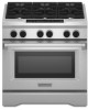
76.2 cm/91.4 cm Oven Schematic for KDRU and YKDRU Models
 |
UPC - 883049156118
View all KitchenAid KDRS467VSS manuals
Add to My Manuals
Save this manual to your list of manuals |
Page 28 highlights
30"/36" (76.2 cm/91.4 cm) Oven Schematic for KDRU and YKDRU Models NOTES: ■ End of line tester is for manufacturing purpose only. ■ Dots indicate connections or splices. ■ Circuit shown in STANDBY/OFF mode with oven door closed. P9-5 P9-6 P9-1 P9-3 Hall Effect Sensor N L2 L1 W R BK R W BK Spare Cooktop LCD Conductivity Sensor P9-1 P9-2 P9-3 P9-4 G GYV Keypad P1 P1-12 P7 P6 P9 User Interface Board P1 P2 Control Panel G GND P2-1 P8-1 Temp Sensor W V P2-1 W BK BK BK Spare 1080 At 21 C (70 F) Communication 1654 At 177 C (350 F) W V P2-2 BK Control Power Transformer BK Meat Probe 78K At 15.6 C (60 F) 37K At 32.2 C (90 F) W OR P2-5 W W P2-6 BK BK T4-4 BK BK T4-3 BR P1-5 BR BR OR OR P1-7 Door Switch (On Latch Assy) BU BU T T P1-4 Latch Switch BK (Operated By Motor) BK T4-2 W W Y Door Lock Latch BK Y P8-5 P9-5 Boiler NTC Pressure Switch Y BR P3-5 P3-4 100K At 25 C (77 F) 6.8K At 100 C (212 F) BK BK Y Y P2-7 P2-8 R R T1-2 R T2-2 End Of Line Tester GND N L2 W R P6 P5 Appliance Manager P7-3 R P7-1 W P8-3 OR Conv. Fan1 OR T3-2 Y Conv. Fan 2 Y Conv. - 2800W T3-3 R R Bake - 3000W T3-4 OR OR In Broil - 3500W T3-1 BU BU Thermal Cutoff (Non-Resettable 338˚F (170˚C) R Out Broil - 30" - 2000W T5-2 BR 36" - 3000W BK BR BK Steam Boiler - 1300W Blower P8-4 R RW P8-6 BK P1-1 R P1-2 Y P1-3 BK P9-2 BK P9-3 R BK W Halogen 25W/120V Bulb Operate In All Modes Except Self-Clean WW BK BK BK Fill Valve W T1-1 R/W T2-1 R/W Spare Steam LEGEND Ground Plug With Receptacle (Chassis) Female With Male Light Connector Connector AC Drive Motor Relay Coil Relay Contact Heating Element Enclosed Thermistor Operated By Door Thermal Cutoff (Non- Thermostat Resettable) Fill Valve 28
-
 1
1 -
2
-
3
-
4
-
5
-
6
-
7
-
8
-
9
-
10
-
11
-
12
-
13
-
14
-
15
-
16
-
17
-
18
-
19
-
20
-
21
-
22
-
 23
23 -
 24
24 -
 25
25 -
 26
26 -
 27
27 -
 28
28 -
 29
29 -
 30
30 -
 31
31 -
 32
32 -
 33
33 -
34
-
35
-
36
-
37
-
38
-
39
-
40
-
41
-
42
-
43
-
44
-
45
-
46
-
47
-
48
-
49
-
50
-
51
-
52
-
53
-
54
-
55
-
56
 |
 |
