KitchenAid KHHC2090SSS Installation Guide - Page 7
Mark Rear Wall, Drill Holes in Rear Wall, Attach Mounting Plate to Wall - microwave
 |
UPC - 883049023984
View all KitchenAid KHHC2090SSS manuals
Add to My Manuals
Save this manual to your list of manuals |
Page 7 highlights
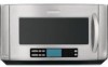
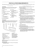
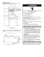
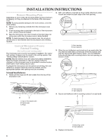
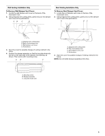
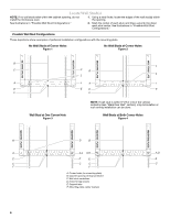
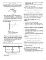
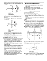
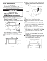
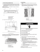
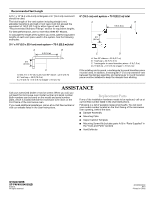
Mark Rear Wall The microwave oven must be installed on a minimum of 1 wall stud, preferably 2, using a minimum of 1 lag screw, preferably 2. 1. Using measuring tape, find and clearly mark the vertical centerline of the opening. A A. Centerline 2. With the support tabs facing forward (see illustrations in "Possible Wall Stud Configurations" in "Locate Wall Stud(s)" section), align the mounting plate center markers to the centerline on the wall, making sure it is level, and that the top of the mounting plate is butted up against the bottom edge of the upper cabinet. NOTE: If the front edge of the upper cabinet is lower than the back edge, lower the mounting plate so that its top is level with the front edge of the cabinet. D A C B A. Rear wall B. Mounting plate C. Top of mounting plate must align with front edge of cabinet. D. Front edge of upper cabinet 3. Holding the mounting plate in place, mark both bottom corner holes. 4. Find the wall stud centerline(s) marked in Step 2 of "Locate Wall Stud(s)," and mark at least 1, preferably 2, hole(s) through the mounting plate, closest to the wall stud centerline(s). See figures 1, 2 and/or 3 in "Possible Wall Stud Configurations" in "Locate Wall Stud(s)" section. The blackened holes in the shaded areas are ideal hole locations. 5. Set the mounting plate aside. Wall Venting Installation Only Upper cabinet bottom ³⁄₈" (1 cm) 4" (10.2 cm) Centerline 6" (15.2 cm) 6" (15.2 cm) 6. Mark the centerline 3/8" (1 cm) down from the bottom edge of the upper cabinet. 7. Using measuring tape, measure out 6" (15.2 cm) on both sides of the centerline, and mark. 8. Measure down 4" (10.2 cm) from the mark made in Step 6, and mark. 9. Using a straightedge, draw the 2 horizontal, level lines through the marks made in steps 6 and 8. 10. Draw the 2 vertical, plumb lines down from the marks made in Step 7 to complete the 12" x 4" (30.5 x 10.2 cm) rectangle. This is the venting cutout area. 11. Cut a 3/4" (19 mm) hole in one corner of the cutout area. 12. Using a keyhole saw, cut out the venting cutout area. Drill Holes in Rear Wall In addition to being installed on at least 1 wall stud, the mounting plate must attach to the wall at both bottom corner holes. If the holes are not over wall studs, use two 1/4-20 x 3" round-head bolts with toggle nuts; if 1 hole is over a wall stud, use 1 lag screw and one 1/4-20 x 3" round-head bolt with toggle nut; or if both holes are over wall studs, use 2 lag screws. Following are 3 installation configurations. Installation for No Wall Studs at Corner Holes (Figures 1 & 2) 1. Drill 3/4" (19 mm) holes through the wall at both bottom corner holes marked in Step 3 of "Mark Rear Wall." 2. Drill 3/16" (5 mm) hole(s) into the wall stud(s) at the hole(s) marked in Step 4 of "Mark Rear Wall." Refer to figures 1 and 2 in "Possible Wall Stud Configurations" in "Locate Wall Stud(s)" section. Installation for Wall Stud at One Corner Hole (Figure 3) 1. Drill a 3/16" (5 mm) hole into the wall stud at the corner hole marked in Step 3 of "Mark Rear Wall." 2. If installing on a second wall stud, drill a 3/16" (5 mm) hole into the wall stud at the other hole marked in Step 4 of "Mark Rear Wall." Refer to Figure 3 in "Possible Wall Stud Configurations" in "Locate Wall Stud(s)" section. 3. Drill a 3/4" (19 mm) hole through the wall at the other corner hole. Installation for Wall Studs at Both Corner Holes (Figure 4) 1. Drill 3/16" (5 mm) holes into the studs at the corner holes marked in Step 3 of "Mark Rear Wall." Attach Mounting Plate to Wall NOTE: Secure the mounting plate to the wall at both bottom corner holes drilled into the wall studs and/or drywall using either 1/4-20 x 3" round-head bolts and toggle nuts or 1/4 x 2" lag screws. Refer to illustrations in "Possible Wall Stud Configurations" in "Locate Wall Stud(s)" section. No Wall Studs at Corner Holes (Figures 1 & 2) NOTE: The mounting plate must be secured to the wall on at least 1 wall stud as well as at both bottom corners. 1. With the support tabs of the mounting plate facing forward, insert 1/4-20 x 3" round-head bolts through both bottom corner holes of mounting plate. 7
-
 1
1 -
 2
2 -
 3
3 -
 4
4 -
 5
5 -
 6
6 -
 7
7 -
 8
8 -
 9
9 -
 10
10 -
 11
11 -
 12
12
 |
 |