KitchenAid KVUB600DSS Use & Care Guide - Page 10
Warning - parts
 |
View all KitchenAid KVUB600DSS manuals
Add to My Manuals
Save this manual to your list of manuals |
Page 10 highlights
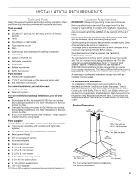
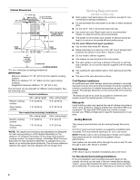
Make Electrical Connection WARNING Electrical Shock Hazard Disconnect power before servicing. Replace all parts and panels before operating. Failure to do so can result in death or electrical shock. 1. Disconnect power. 2. Remove terminal box cover. 3. Remove the knockout in the terminal box and install a UL listed or CSA approved ¹⁄₂" strain relief. 4. Run home power supply wiring through ¹⁄₂" strain relief into terminal box. AB C D E B I F G H A. Terminal box cover B. Screws C. Home power supply D. ½" UL listed or CSA approved strain relief E. Terminal box F. Black wires G. White wires H. UL listed wire connectors I. Green (or bare) wires connected to yellow-green wires 5. Use UL listed wire connectors and connect white wires (B) together. 6. Use UL listed wire connectors and connect black wires (C) together. WARNING Electrical Shock Hazard Electrically ground blower. Connect ground wire to green and yellow ground wire in terminal box. Failure to do so can result in death or electrical shock. 7. Connect green (or bare) ground wire from home power supply to the 2 yellow-green ground wires (D) in terminal box using UL listed wire connectors. 8. Tighten strain relief screw. 9. Install terminal box cover. 10. Reconnect power. Optional Power Cord Kit Installations For optional power cord kit installations, follow the instructions supplied with the power cord kit. See the "Assistance or Service" section for information on ordering. NOTE: Use only with range hood cord connection kits that have been investigated and found acceptable for use with this model range hood. Install Vent Covers 1. When using both upper and lower vent covers, push lower cover down onto hood and lift upper cover to ceiling and install with 2 - 2.9 x 6.5 mm screws. NOTE: For vented installations, the upper vent cover may be reversed to hide slots. D C C A B A. Upper vent cover B. Lower vent cover C. 2.9 x 6.5 mm screws D. Bracket Complete Installation 1. For non-vented (recirculating) installations only, install charcoal filters over grille on blower housing. See the "Range Hood Care" section. 2. Install metal filters. See the "Range Hood Care" section. 3. Check the operation of the range hood blower and light. See the "Range Hood Use" section. NOTE: To get the most efficient use from your new range hood, read the "Range Hood Use" section. 10
-
 1
1 -
2
-
3
-
4
-
 5
5 -
 6
6 -
 7
7 -
 8
8 -
 9
9 -
 10
10 -
 11
11 -
 12
12 -
 13
13 -
 14
14 -
 15
15 -
16
-
17
-
18
-
19
-
20
-
21
-
22
-
23
-
24
-
25
-
26
-
27
-
28
-
29
-
30
-
31
-
32
 |
 |
