LG 26LC7D Owner's Manual (English) - Page 20
VCR SETUP, When connecting with an antenna - tv remote
 |
UPC - 719192171350
View all LG 26LC7D manuals
Add to My Manuals
Save this manual to your list of manuals |
Page 20 highlights
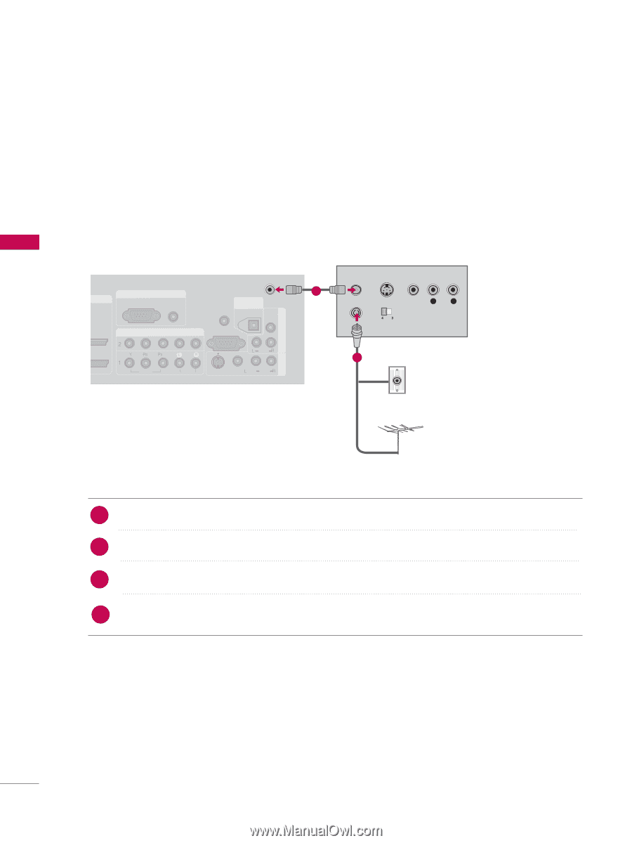
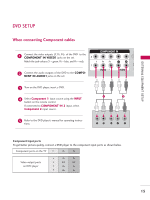
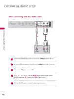
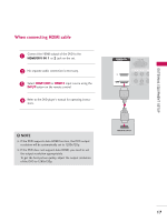
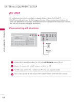
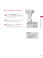
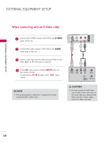
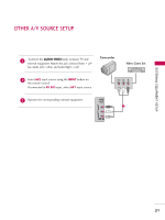
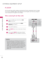
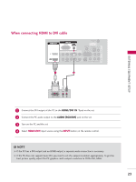
EXTERNAL EQUIPMENT SETUP AV IN 1 COMPONENT IN 2 EXTERNAL EQUIPMENT SETUP 1(DVI) VIDEO AUDIO VIDEO ( ) AUDIO VCR SETUP I To avoid picture noise (interference), leave an adequate distance between the VCR and TV. I If the 4:3 picture format is used; the fixed images on the sides of the screen may remain visible on the screen. This phenomenon is common to all manufacturers and in consequence the manufacturer's warranty does not cover the product bearing this phenomenon. When connecting with an antenna HDMI/DVI IN 2 1 (DVI) RGB IN RGB (PC) AUDIO (RGB/DVI) COMPONENT IN ANTENNA IN REMOTE CONTROL IN DIGITAL AUDIO OUT OPTICAL VIDEO RS-232C IN (CONTROL & SERVICE) AUDIO VIDEO AUDIO S-VIDEO VIDEO (MONO) AUDIO AV IN 1 AV OUT 1 ANT OUT S-VIDEO VIDEO L R ANT IN OUTPUT SWITCH 2 Wall Jack HDMI/DVI IN 2 1 (DVI) Antenna 1 Connect the RF antenna out socket of the VCR to the ANTENNA I N socket on the set. 2 Connect the antenna cable to the RF antenna in socket of the VCR. 3 Set VCR output switch to 3 or 4 and then tune TV to the same programme number. 4 Insert a video tape into the VCR and press PLAY on the VCR. (Refer to the VCR owner's manual.) 18
-
 1
1 -
2
-
3
-
4
-
5
-
6
-
7
-
8
-
9
-
10
-
11
-
12
-
13
-
14
-
 15
15 -
 16
16 -
 17
17 -
 18
18 -
 19
19 -
 20
20 -
 21
21 -
 22
22 -
 23
23 -
 24
24 -
 25
25 -
26
-
27
-
28
-
29
-
30
-
31
-
32
-
33
-
34
-
35
-
36
-
37
-
38
-
39
-
40
-
41
-
42
-
43
-
44
-
45
-
46
-
47
-
48
-
49
-
50
-
51
-
52
-
53
-
54
-
55
-
56
-
57
-
58
-
59
-
60
-
61
-
62
-
63
-
64
-
65
-
66
-
67
-
68
-
69
-
70
-
71
-
72
-
73
-
74
-
75
-
76
-
77
-
78
-
79
-
80
-
81
-
82
-
83
-
84
-
85
-
86
-
87
-
88
-
89
-
90
-
91
-
92
-
93
-
94
-
95
-
96
-
97
-
98
 |
 |