LG 42PM4M Owners Manual - Page 9
Connection Options - specifications
 |
View all LG 42PM4M manuals
Add to My Manuals
Save this manual to your list of manuals |
Page 9 highlights
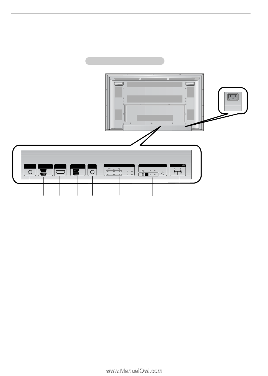
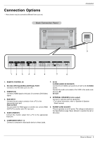
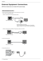
Connection Options - Here shown may be somewhat different from your set. Back Connection Panel Introduction AC IN 9 REMOTE CONTROL IN RS-232C (CONTROL&SERVICE) HDMI/DVI IN OUT IN RGB IN OUT AUDIO (RGB/DVI) COMPONENT IN VIDEO L-AUDIO-R 1 2 AV IN VIDEO L-AUDIO-R S-VIDEO AV OUT EXTERNAL SPEAKER R L 1 2 3 4 5 6 7 8 1. REMOTE CONTROL IN 2. RS-232C INPUT(CONTROL&SERVICE) PORT Connect to the RS-232C port on a PC. 3. HDMI/DVI IN Connect a HDMI signal to this jack. Or connect a DVI(Video) signal. 4. RGB INPUT Connect the set output connector from a PC to the appropriate input port. RGB OUTPUT You can watch the RGB signal on another set, connect RGB OUTPUT to another set's PC input port. 5. AUDIO (RGB/DVI) Connect the monitor output from a PC to the appropriate input port. 7. AV IN S-VIDEO/AUDIO IN SOCKETS Connect the S-VIDEO out socket of an VCR to the S-VIDEO socket. Connect the audio out sockets of the VCR to the audio sockets as in AV. AV OUT 8. EXTERNAL SPEAKER (8 ohm output) Connect to optional external speaker(s). * For further information, refer to 'Speaker & Speaker Stand' manual. 9. POWER CORD SOCKET This set operates on an AC power. The voltage is indicated on the Specifications page. Never attempt to operate the set on DC power. 6. COMPONENT INPUT 1-2 Connect a component video/audio device to these jacks. Owner's Manual 9
-
 1
1 -
2
-
3
-
 4
4 -
 5
5 -
 6
6 -
 7
7 -
 8
8 -
 9
9 -
 10
10 -
 11
11 -
 12
12 -
 13
13 -
 14
14 -
15
-
16
-
17
-
18
-
19
-
20
-
21
-
22
-
23
-
24
-
25
-
26
-
27
-
28
-
29
-
30
-
31
-
32
-
33
-
34
-
35
-
36
-
37
-
38
-
39
-
40
-
41
-
42
-
43
-
44
 |
 |