LG BG-101A Service Manual - Page 8
Electrical Parts
 |
View all LG BG-101A manuals
Add to My Manuals
Save this manual to your list of manuals |
Page 8 highlights
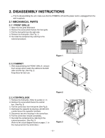
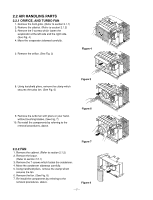
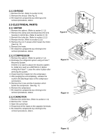
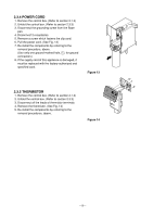
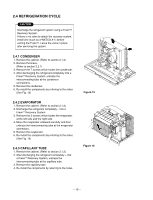
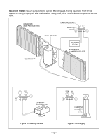
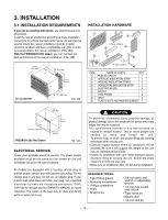
2.2.3 SHROUD 1. Remove the fan. (Refer to section 2.2.2) 2. Remove the shroud. (See Fig. 9) 3. Re-install the components by referring to the removal procedures, above. 2.3 ELECTRICAL PARTS 2.3.1 MOTOR 1. Remove the cabinet. (Refer to section 2.1.2) 2. Remove the clamp cord and disconnect the wire housing in control box. (Refer to section 2.1.3) 3. Remove the turbo fan. (Refer to section 2.2.2) 4. Remove the fan. (Refer to section 2.2.2) 5. Remove the 4 or 2 screws which fasten the motor. (See Fig. 10) 6. Remove the motor. 7. Re-install the components by referring to the removal procedures, above. 2.3.2 COMPRESSOR 1. Remove the cabinet. (Refer to section 2.1.2) 2. Discharge the refrigerant system using a FreonTM Recovery System. If there is no valve to attach the recovery system to, install one (such as a WATCO A-1) before venting the FreonTM . Leave the valve in place after servicing the system. 3. Disconnect the 3 leads from the compressor. 4. After purging the unit completely, unbraze the suction and discharge tubes at the compressor connections. 5. Remove the 3 nuts and the 3 washers which fasten the compressor. (See Fig. 11) 6. Remove the compressor. 7. Re-install the components by referring to the removal procedures, above. 2.3.3 CAPACITOR 1. Remove the control box. (Refer to section 2.1.3) 2. Remove the 1 screw 3. Open the control box 4. Disconnect all the leads on the capacitor terminals. 5. Re-install the components by referring to the removal procedures, above. Figure 9 Figure 10 Figure 11 ESnaevCregoryol Fan MODE Timer TIMER FF3F2H1MILGEOHDW TEMP 'F SPFEAEND POWER -8- Figure 12
-
 1
1 -
2
-
 3
3 -
 4
4 -
 5
5 -
 6
6 -
 7
7 -
 8
8 -
 9
9 -
 10
10 -
 11
11 -
 12
12 -
 13
13 -
14
-
15
-
16
-
17
-
18
-
19
-
20
-
21
-
22
-
23
-
24
-
25
-
26
-
27
-
28
-
29
-
30
-
31
-
32
-
33
-
34
-
35
-
36
-
37
-
38
-
39
 |
 |
