LG BG-81A Owners Manual - Page 16
Procedure C
 |
View all LG BG-81A manuals
Add to My Manuals
Save this manual to your list of manuals |
Page 16 highlights
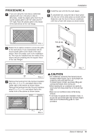
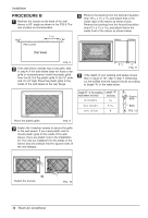
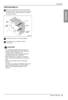
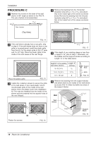
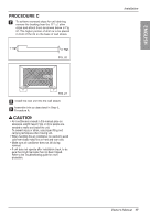
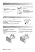
Installation PROCEDURE C 1 Redirect the louvers at the back of the wall sleeve to 60° angle as shown in the FIG 14. The use of pliers is recommended. 60° Rear Louvers 7 3/32" 60° (Top View) FIG. 14 2 If the wall sleeve already has a rear grille, skip to step 4. If the wall sleeve does not have a rear grille or louvered panel, install the plastic grille from the kit. Cut the plastic grille to 26-1/2" wide and 15-1/2" high. Place the plastic grille to the inside of the wall sleeve at the rear flange. 4 Remove the backing from the Horizontal Insulation strip 237/32 x 13/8 x 13/16 and attach that to the inside right of the sleeve as shown below. Remove the backing from the Around Insulation strip 5927/32 x 13/8 x 13/8 and attach that to the inside front of the sleeve as shown below. Around Insulation Horizontal Insulation Indoor Outdoor 8 1/2" FIG. 17 5 If the depth of your existing sleeve is less than or equal to 18", skip to step 7. Otherwise, cut the baffles and the support blocks according to Length "A" in the table below. Place the plastic grille FIG. 15 3 Fasten the 4 washer screws to secure the grille to the wall sleeve. If you need plastic nuts to mount plastic grille to the inside of the wall sleeve, there are plastic nuts in the installation kit. The nuts are installed from the inside of the sleeve and are pressed into the square holes of the rear flanges. Depth"D" of the existing Length "A" wall sleeve (inches) (inches) 18 D 18-5/8 3/4 18-5/8 D 19-3/4 1-3/4 19-3/4 D 22 4 A Support Block Baffle A FIG. 18 6 Remove the backing from the support blocks and attach them to the inside of the wall sleeve as shown FIG 19. Slide the baffle into slots of the support blocks Wall (7 3/32") Wall Sleeve Baffle or Fasten the screws FIG. 16 Front Support Block FIG. 19 16 Room Air Conditioner
-
 1
1 -
2
-
3
-
4
-
5
-
6
-
7
-
8
-
9
-
10
-
 11
11 -
 12
12 -
 13
13 -
 14
14 -
 15
15 -
 16
16 -
 17
17 -
 18
18 -
 19
19 -
 20
20 -
 21
21 -
22
-
23
-
24
-
25
-
26
-
27
-
28
-
29
-
30
-
31
-
32
-
33
-
34
-
35
-
36
-
37
-
38
-
39
-
40
-
41
-
42
-
43
-
44
-
45
-
46
-
47
-
48
-
49
-
50
-
51
-
52
-
53
-
54
-
55
-
56
-
57
-
58
-
59
-
60
-
61
-
62
-
63
-
64
-
65
-
66
-
67
-
68
-
69
-
70
-
71
-
72
 |
 |
