LG DLE2512W Service Manual - Page 28
Test 5 - flashing
 |
View all LG DLE2512W manuals
Add to My Manuals
Save this manual to your list of manuals |
Page 28 highlights
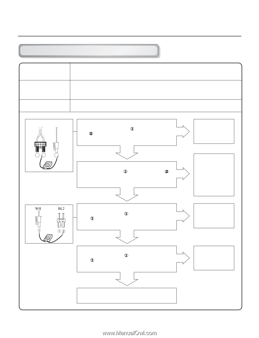
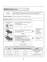
Test 5 Door switch test Caution Before measuring resistance, be sure to turn Power off, and do voltage discharge. (When discharging, contact the metal plug of Power cord with earth line.) Door Opening is not sensed.(During operation, when opening Door, Drum motor and Trouble Symptom Heater run continuously) Door Close is not sensed. (Drum motor will not operate. Display will flash at 0.5 second intervals.) Measurement Condition After turning Dryer Power Off, measure resistance. BK2 WH1 12 1 1 Measure while Door is closed. Check it resistance is below 2500 Ω between WH1- (White wire) and BK2- Connector WH1,BL2 after taking WH1,BL2 out from Controller. YES NO Measure while Door is open. Check it resistance is 300~60 Ω between WH1- (White wire) and BK2(Black wire). Connector WH1,BL2 after taking NO WH1,BL2 out from Controller. YES • Door switch Check (Refer to Component testing.) • Check Lamp. (When opening Lamp, replace then measure again.) • Door switch Check(Refer to Component testing.) Measure while Door is open. Check it resistance is below 1 Ω between BL2- (Yellow wire) and WH1- (White wire) after taking Connector WH1,BL2 out from Controller. YES NO • Door switch Check (Refer to Component testing.) Measure while Door is closed. Check it resistance is below 1 Ω between BL2- (Yellow wire) and WH1- (White wire) after taking Connector WH1,BL2 NO out from Controller. YES • Door switch Check (Refer to Component testing.) Check Controller. Check Harness-linking connector. 27
-
 1
1 -
2
-
3
-
4
-
5
-
6
-
7
-
8
-
9
-
10
-
11
-
12
-
13
-
14
-
15
-
16
-
17
-
18
-
19
-
20
-
21
-
22
-
 23
23 -
 24
24 -
 25
25 -
 26
26 -
 27
27 -
 28
28 -
 29
29 -
 30
30 -
 31
31 -
 32
32 -
 33
33 -
34
-
35
-
36
-
37
-
38
-
39
-
40
-
41
-
42
-
43
-
44
-
45
 |
 |