LG DLG2532W Service Manual - Page 11
Component Testing Information - reset switch
 |
View all LG DLG2532W manuals
Add to My Manuals
Save this manual to your list of manuals |
Page 11 highlights
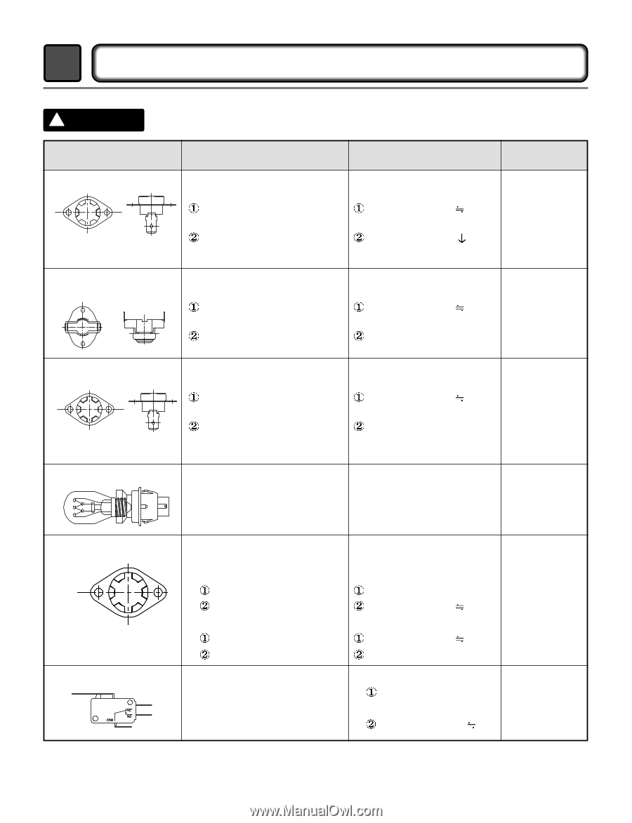
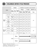
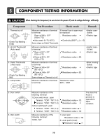
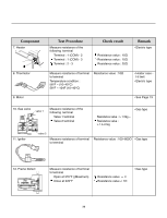
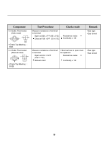
5 COMPONENT TESTING INFORMATION ! CAUTION When checking the Component, be sure to turn the power off, and do voltage discharge sufficiently. Component 1. Thermal cut off • Check Top Marking : N130 2. Hi limit Thermostat (Auto reset) 3. Outlet Thermostat ( Auto reset) • Check Top Marking : N85 4. Lamp holder Test Procedure Check result Remark Measure resistance of terminal If thermal fuse is open must • Heater case- to terminal be replaced Safety Open at 266 ± 12°F (130 ± 7°C) Resistance value ∞ • Electric type Auto reset -31°F (-35°C) Continuity (250°F ) < 1Ω Same shape as Outlet Thermostat. Measure resistance of terminal to terminal Open at 257 ± 9°F (125 ± 5°C) Close at 221 ± 9°F (105 ± 5°C) Resistance value ∞ Resistance value < 5Ω Measure resistance of terminal to terminal Open at 185 ± 9°F (85 ± 5°C) Close at 149 ± 9°F (65 ± 5°C) Same shape as Thermal cut off. Resistance value ∞ Resistance value < 5Ω Measure resistance of terminal Resistance value : to terminal 80Ω ~ 100Ω • Heater case Hi limit • Electric type • Blow housing Safety • Electric type 5. Door switch 6. Idler switch Measure resistance of the following terminal 1) Door switch knob : open Terminal : "COM" - "NC" (1-3) Terminal : "COM" - "NO" (1-2) 2) Door switch push : push Terminal : "COM" - "NC" (1-3) Terminal : "COM" - "NO" (1-2) Resistance value < 1Ω Resistance value ∞ Resistance value ∞ Resistance value < 1Ω The state that Knob is pressed is opposite to Open condition. Measure resistance of the following terminal : "COM - NC" 1. lever open Resistance value < 1Ω 2. Lever push (close) Resistance value ∞ 10
-
 1
1 -
2
-
3
-
4
-
5
-
 6
6 -
 7
7 -
 8
8 -
 9
9 -
 10
10 -
 11
11 -
 12
12 -
 13
13 -
 14
14 -
 15
15 -
 16
16 -
17
-
18
-
19
-
20
-
21
-
22
-
23
-
24
-
25
-
26
-
27
-
28
-
29
-
30
-
31
-
32
-
33
-
34
-
35
-
36
-
37
-
38
 |
 |