LG GCE-8240B Owners Manual - Page 8
Location and Function of Controls
 |
View all LG GCE-8240B manuals
Add to My Manuals
Save this manual to your list of manuals |
Page 8 highlights
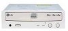
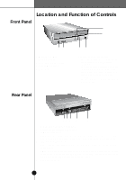
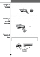
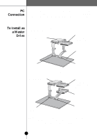
DirectCDTM v2.5b(s) Location and Function of Controls Front Panel 6 5 READ WRITE 12 1. Headphone jack 2. Volume control 3. Emergency Eject Hole 4. Stop/Eject button 5. Disc tray 34 6. Drive activity indicators Two colored LEDs are used to indicate the operation of CD-R/RW Drive. (1) Read The orange color is displayed when the spindle motor begins the Spin up operation: accessing data, reading data, playing Audio, and up loading tray. (2) Write The green color is flashed during disc writing sessions. Rear Panel DIGITAL AUDIO R ANALOG AUDIO G L C S S L M A 39 40 D G INTERFACE POWER 1 +5 GND +12 2 12 3 4 5 1. Digital Audio Output Connector 2. Analog Audio Output Connector 3. Jumper Connector This jumper determines whether the drive is configured as a master or slave. Changing the master-slave configuration takes effect after power-on reset. 4. IDE Interface Connector Connect to the IDE (Integrated Device Electronics) Interface using a 40-pin flat IDE cable. NOTE : Do not connect or disconnect the cable when the power is on, as this could cause a short circuit and damage the system. Always turn the power OFF when connecting or disconnecting the cable. 5. Power Connector 5
-
 1
1 -
2
-
 3
3 -
 4
4 -
 5
5 -
 6
6 -
 7
7 -
 8
8 -
 9
9 -
 10
10 -
 11
11 -
 12
12 -
 13
13 -
14
-
15
-
16
-
17
-
18
-
19
 |
 |
