LG GR-J303TS Service Manual - Page 17
Buzzer driving circuit located on display PCB, 2-5. SWITCH INPUT CIRCUIT, LED MODULE TYPE
 |
View all LG GR-J303TS manuals
Add to My Manuals
Save this manual to your list of manuals |
Page 17 highlights
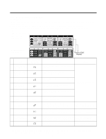
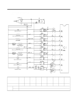
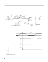
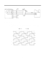
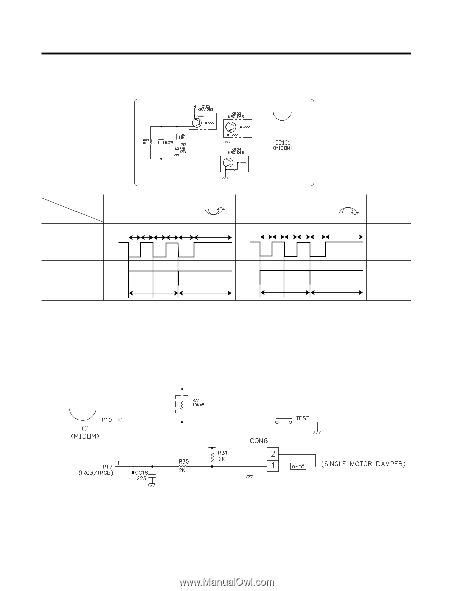
(2) Buzzer driving circuit (located on display PCB) g Only the buzzer sound for the Lock/Unlock operation is shown in this SVC technical manual. LED MODULE TYPE 78 P35 (INT1) 79 P36 (PWM3/TC3/PDO3) Status Measuring Ex) Lock: "Ding-D-Dong" sound Ex) Lock: "Ding-D-Dong" sound Off point 45ms 45ms 45ms 45ms 70ms 750ms 45ms 45ms 45ms 45ms 70ms 750ms IC101 (Pin 3/61) 5V 5V 5V 0V 0V 5V 5V IC101 (Pin 2/62) 0V 0V 1046.5Hz 1174.7Hz 1318.5Hz 0V 1568.0Hz 1318.5Hz 1046.5Hz 3-2-5. SWITCH INPUT CIRCUIT Following circuits are input circuits for detecting signal of the test switch for checking refrigerator or the reed switch of the single motor damper. REED Switch - 17 -
-
 1
1 -
2
-
3
-
4
-
5
-
6
-
7
-
8
-
9
-
10
-
11
-
 12
12 -
 13
13 -
 14
14 -
 15
15 -
 16
16 -
 17
17 -
 18
18 -
 19
19 -
 20
20 -
 21
21 -
 22
22 -
23
-
24
-
25
-
26
-
27
-
28
-
29
-
30
-
31
-
32
-
33
-
34
-
35
-
36
-
37
-
38
-
39
-
40
-
41
-
42
-
43
-
44
-
45
-
46
 |
 |
(2) Buzzer driving circuit (located on display PCB)
g
Only the buzzer sound for the Lock/Unlock operation is shown in this SVC technical manual.
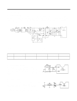
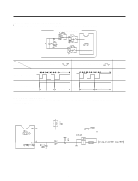
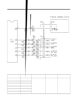
3-2-5. SWITCH INPUT CIRCUIT
Following circuits are input circuits for detecting signal of the test switch for checking refrigerator or the reed switch of the
single motor damper.
- 17 -
REED Switch
78
79
P35
(INT1)
P36
(PWM3/TC3/PDO3)
LED MODULE TYPE
Ex) Lock: "Ding-D-Dong" sound
Ex) Lock: "Ding-D-Dong" sound
Off
IC101 (Pin 3/61)
5V
IC101 (Pin 2/62)
0V
Measuring
point
Status
45ms
1046.5Hz
1174.7Hz
1318.5Hz
45ms 45ms 45ms 70ms
750ms
5V
0V
5V
0V
45ms
1568.0Hz
1318.5Hz
1046.5Hz
45ms 45ms 45ms 70ms
750ms
5V
0V
5V
0V