LG LP120HED1 Owners Manual - Page 19
ooff45£mL
 |
View all LG LP120HED1 manuals
Add to My Manuals
Save this manual to your list of manuals |
Page 19 highlights
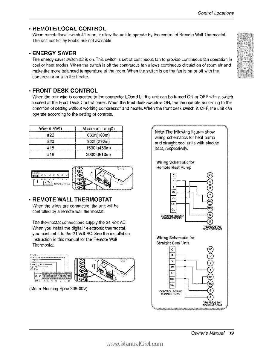
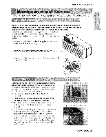
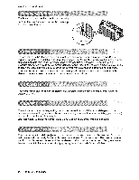
Control Locations '. REMOTE/LOCAL CONTROL When remoteil_al swiitch #1 is on, it anew the unit toi operate by the control of Remot8 Wall Therm_t. The unit con#o! by knobs we not availaNe, • ENERGY SAVER The energy saver _¢.4tch#2 is o,n This switch is set at continuous fan to provide continu,ous _n eperatJon in co,o,_or heat mo,_s. When the switch is off the _ntinuous dan aH_s continuous drculation o,1r_3m air and m,_e 'the more balan_d temperature o_the r_m, When the switch is on the '{_ is on or off with the co_ressor or with the heater. . FRONT DESK CONTROL _¢_en the pa,ir wire is conn_ed to the connecter LO_d LL the unit can be turned ON or OFF with a switch i_ated at the _ont D,_k Contro_ paJ_eLWhen the fro_ _sk switch is ON, the fan _erate aocording to, the condition of setting without working compres_r and heater, When the front d_k _witch is OFE the unit can o_rate a_ording to the setting of controls. .........W...k..e M...:._..i.m...,.u..m...._..n.._..t.h Note:The bllo_ng figures show wiring schem._cs lor heat pu_ 9 2....Z.....O.....m a..n.d...s.t.r.a.i.g.h..t..c.o..o.l..u..n.i.t.s..w.._.h.. electric 8 o..o..f.f.(..4..5..£..m...L h.e.a..t,..r.e.s._..c.f.iv..e.ly............ #16 _0_t(6'10m) Wiring Schematic for Remote Neat Pump ® , REMOTE WALL THERMOSTAT When the wires are connectS, the unit wili cointro,lledbly a remote wa!l thermos_'t. The thermostat conne_ions supply the 24 Volt AC_ When you instal!the, digi_l / e_ctronic thermostat you mu_ set it to the 24 Vo,_AC. See the instali[l_:ion Instruction in this manual for the Remote Wall Thermost_. -_- CONN_O_ Wida$ _hemat_e for ® '_M_TAT CON_ECTIONS ® ® (Molex Housing S_c 396,-_V) c_nr_ _o_o _ONS ® TH_PP_TAT Owne, s Manual 19
-
 1
1 -
2
-
3
-
4
-
5
-
6
-
7
-
8
-
9
-
10
-
11
-
12
-
13
-
 14
14 -
 15
15 -
 16
16 -
 17
17 -
 18
18 -
 19
19 -
 20
20 -
 21
21 -
 22
22 -
 23
23 -
 24
24 -
25
-
26
-
27
 |
 |