LG LST-4200A Service Manual - Page 43
ATSC Front-End part
 |
View all LG LST-4200A manuals
Add to My Manuals
Save this manual to your list of manuals |
Page 43 highlights
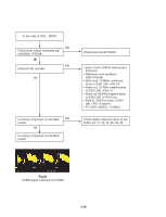
6. ATSC Front-End part Start YES NO Is power charging normal(IC500)? YES Is RF input signal normal? NO (using spectrum analyzer) YES NO Check error signal (IC500(22)). (Oscilloscope is used) High : Normal, Low : Abnormal YES Check output data of tuner(IC500). NO (Fig. 01) (pin 28,29,30,31,32,33,34,35), packet clock ( Fig.02)(pin 27) and byte clock(pin 36) (Fig.03). YES END Check the power line, referring to circuit diagram. (+5V_Alive, +5V, +30V, +1.8, +3.3V) Check antenna connection condition. Check voltage between R511 and earth. 5V : Normal, 0~4V : Q501, Q502 should be replaced. Check connection between tuner and PCB. 3-34
-
 1
1 -
2
-
3
-
4
-
5
-
6
-
7
-
8
-
9
-
10
-
11
-
12
-
13
-
14
-
15
-
16
-
17
-
18
-
19
-
20
-
21
-
22
-
23
-
24
-
25
-
26
-
27
-
28
-
29
-
30
-
31
-
32
-
33
-
34
-
35
-
36
-
37
-
 38
38 -
 39
39 -
 40
40 -
 41
41 -
 42
42 -
 43
43 -
 44
44 -
 45
45 -
 46
46 -
 47
47 -
 48
48 -
49
-
50
-
51
-
52
-
53
-
54
-
55
-
56
-
57
-
58
-
59
-
60
-
61
-
62
-
63
-
64
-
65
-
66
-
67
-
68
-
69
-
70
-
71
-
72
-
73
-
74
-
75
-
76
 |
 |

3-34
6. ATSC Front-End part
Is power charging normal(IC500)?
Is RF input signal normal?
(using spectrum analyzer)
Check error signal (IC500(22)).
(Oscilloscope is used) High : Normal,
Low : Abnormal
Check output data of tuner(IC500).
(Fig. 01)
(pin 28,29,30,31,32,33,34,35),
packet clock ( Fig.02)(pin 27) and
byte clock(pin 36) (Fig.03).
Check connection between tuner and
PCB.
END
Start
Check the power line, referring to
circuit diagram. (+5V_Alive, +5V,
+30V, +1.8, +3.3V)
Check antenna connection
condition.
Check voltage between R511 and
earth. 5V : Normal, 0~4V : Q501,
Q502 should be replaced.
NO
NO
NO
NO
YES
YES
YES
YES
YES