LG MA748W 01 Service Manual - Page 17
Assembly, Removal, Interlock, System, Nimany
 |
View all LG MA748W 01 manuals
Add to My Manuals
Save this manual to your list of manuals |
Page 17 highlights
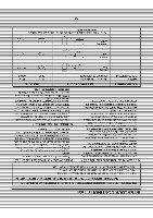
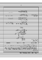
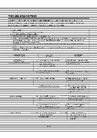
K. PCB ASSEMBLY REMOVAL 1) Remove-the-control panel assemblTtmrttiecavity. (flefertcrcontrol panel assembly removal on previeus-page7) 2) Remove screws which hold the PCB SUB ASS'Y to the control panel. 3) Disconnect the flat cable from the PCB SUB A-STY-and take o Control Panel PCB Sub As L. INTERLOCK SYSTEM 1:)EttlitlEttaeltritl:CHANISM - file door-I.ock-rnechanism-IS-a-clevice which has been specially designed to eliminate completely microwave activity when the door is opcncd during cooking=a-nd thus to prevent the danger resulting from the-microwave leakage. 2)-MOUNTI SECONDARY SWI i CHES TO THE LATCH BOARD ADJUSTMENT nimAny SWITCH MONITOR WIT H SECONDARY SWITC 0 3) INSTALLATION AND ADJUSTMENTO- F-THE LATCH BOARu i U I HE OVEN ASSEMBLY • Mount the latch board to the oven assembly. • Adjust the latch board in the arrow-direction so that oven door will not have any play-Ill-It-when the-door is closed. • Tighten the mounting screw. • Check-for play in the door-by-pushing-thedoor- releas_button.IXor movement shouldbe-less_ than 0.5 mm. (1/64 Inch) n't push the dour rebate bultun while-rnelking adjustment. Make_st ratch moves smoothly after_allu completecrand-that the-screws die light. Make sure the primary, monitor, and secondary switches operate properly by following the continuity test procedure 5-6
-
 1
1 -
2
-
3
-
4
-
5
-
6
-
7
-
8
-
9
-
10
-
11
-
 12
12 -
 13
13 -
 14
14 -
 15
15 -
 16
16 -
 17
17 -
 18
18 -
 19
19 -
 20
20 -
 21
21 -
 22
22 -
23
-
24
-
25
-
26
-
27
-
28
-
29
-
30
-
31
-
32
-
33
-
34
-
35
 |
 |
