Lantronix EMG 8500 - Edge Management Gateway EMG Quick Start Guide - Page 1
Lantronix EMG 8500 - Edge Management Gateway Manual
 |
View all Lantronix EMG 8500 - Edge Management Gateway manuals
Add to My Manuals
Save this manual to your list of manuals |
Page 1 highlights
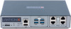
EMG™ 8500 Quick Start Guide Edge Management Gateway ! Thank you for choosing Lantronix. Please register the EMG 8500 in order to receive notifications for firmware and documentation updates at www.lantronix.com/product-registration. WHAT'S IN THE BOX Quick Start Guide START EMG 8500 EMG851210SP with USB and RJ45 FRUs shown. Additional FRU combinations are available. Accessories External Universal AC (100W, 12V) Power Supply North American Power Cord - 110V AC power cord, 8 ft (2.43m), RoHS RJ45 to DB9F Adapter RJ45 to RJ45, CAT5 Cable, 6.6 ft (2 m) RJ45 Loopback Cable Rubber feet with adhesive Additional I/O and Connectivity FRUs are available and sold separately. Part Number ACC-520-0164-00 ACC-500-041-R ACC-200.2070A ACC-200.0062 ACC-500-153 120-008-R varies 1. HARDWARE OVERVIEW Front View Back View Quantity 1 1 1 1 1 4 pieces varies *DIO LEDs Console Port Micro SD USB Bay 1 Bay 2 Device Ports (Modular) Bay 1 Bay 2 Connectivity Ports (Modular) Power Ethernet SFP input The EMG 8500 unit offers up to 8 RJ45 (RS-232) or USB serial device port connections in 2 user-swappable, front I/O module device bays. *Front DIO adapter is available and sold separately. The back of the EMG 8500 unit offers up to 2 connectivity ports for out-of-band management in 2 user-swappable module bays. 2. CONNECTING THE EMG 8500 The front console port allows a dumb terminal or PC with terminal emulation software to locally access management functions and connected devices. The device ports allow simple and flexible connections to serial devices using adapters and a standard CAT5 cable. Connect one end of the CAT5 cable to the device port and the other end to an adapter that attaches to the serial console of the target system. The default communication parameters for the device ports and console ports are: • 9600 baud • 1 stop bit • 8 data bits • No flow control • No parity Note: EMG 8500 device ports are reversed by default, and are software configurable. Default Pin Assignments Console Port (RS-232) Device Ports (RS-232) Reversed by Default 1. RTS 2. DTR 3. TX 4. GND 5. GND 6. RX 7. DSR 8. CTS (Out) (Out) (Out) (In) (In) (In) Not Reversible 1. CTS 2. DSR 3. RX 4. GND 5. GND 6. TX 7. DTR 8. RTS (In) (In) (In) (Out) (Out) (Out) Software Reversible 3. HARDWARE INSTALLATION 1. Install the unit on a desktop or other flat, horizontal surface. Rack mount and wall mount kits are available as optional accessories. 2. Install the I/O modules on the front of the unit and the connectivity modules on the back. Warning: Always remove the power cord prior to installing or removing a connectivity or I/O module. Failure to do so could damage the unit. 3. Connect the equipment to the device ports on the front of the unit using the appropriate cables and adapters. 4. Connect the unit to the network using the upper network port (Ethernet 1 or SFP 1). 5. Connect the power cord to apply power. 6. The top front LED turns green to indicate that power is ON and at least one of the Ethernet ports has a link or both Ethernet ports are disabled. The LED blinks red if none of the enabled Ethernet ports has a link. 7. Wait about a minute and a half for the boot process to complete. The first time you power up the EMG unit, Eth1 tries to obtain its IP Address via DHCP. Warning: If rack mounting the EMG, do not block the air vents on the sides of the unit. If mounted in an enclosed rack, it is recommended that the rack have a ventilation fan. 1
-
 1
1 -
 2
2
 |
 |
