Lantronix PremierWave 2050 Integration Guide - Page 7
: Introduction, About the Integration Guide
 |
View all Lantronix PremierWave 2050 manuals
Add to My Manuals
Save this manual to your list of manuals |
Page 7 highlights
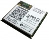
1: Introduction About the Integration Guide This user guide provides the information needed to integrate the Lantronix® PremierWave® 2050 family of products into customer-printed circuit boards. This manual is intended for engineers responsible for integrating the PremierWave 2050 enterprise Wi-Fi® IoT module into their product. This document provides instruction for connecting to the various module pin function groups as well as general module placement and mounting. For detailed technical and compliance specifications please refer to the PremierWave 2050 Enterprise Wi-Fi IoT Module Datasheet available at www.lantronix.com/support/documentation. The table below describes the integration guide sections. Table 1-1 PremierWave 2050 Integration Guide Sections Section PremierWave 2050 Features PremierWave 2050 Block Diagram Signal Descriptions Antenna Interface Antenna Placement Using the RF1 Signal Pin Serial Interface Ethernet Interface USB Device Port USB Host Port LEDs General Purpose IO Pins Reset Pins Mounting Instructions and PCB Footprint Product Information Label Evaluation Board Schematic Description Provides an overview of the module functions and mechanical drawing Shows the module functional blocks Provides signal descriptions and pinout information Lists the antennas pre-certified for use with the module Provides a general recommendation for antenna placement This section is reserved for a future off module antenna connection option Provides an example on how to connect the unit to external RS232/485/422 networks Gives an example on how to connect the module Ethernet Provides an example on how to connect the unit up as a USB device port Provides an example on how to connect the module USB host ports Describes the module LED connections Describes the module GPIO connections Describes the module RESET, DEFAULT, and WAKE pins Provides the module PCB footprint and solder profile Provides an image and description of the unit label contents Provides the PremierWave 2050 evaluation board schematic. PremierWave® 2050 Enterprise Wi-Fi® IoT Module Integration Guide 7
-
 1
1 -
 2
2 -
 3
3 -
 4
4 -
 5
5 -
 6
6 -
 7
7 -
 8
8 -
 9
9 -
 10
10 -
 11
11 -
 12
12 -
13
-
14
-
15
-
16
-
17
-
18
-
19
-
20
-
21
-
22
-
23
-
24
-
25
-
26
-
27
-
28
-
29
-
30
-
31
-
32
-
33
-
34
-
35
-
36
-
37
-
38
 |
 |
