Lantronix PremierWave SE1000 PremierWave - Embedded SoM - Integration Guide - Page 13
Antenna Placement, WLAN LED, Ethernet Input/Output, See the Lantronix app note
 |
View all Lantronix PremierWave SE1000 manuals
Add to My Manuals
Save this manual to your list of manuals |
Page 13 highlights
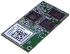
2: Description and Specifications Antenna Placement The PremierWave EN module has an option for an on-board chip antenna. When designing the PremierWave EN system on module to a mating board, it is important to consider the final installation of the unit and its location with respect to connecting access points. The PremierWave EN module should be placed such that the chip antenna has as clear as possible path to the connecting access point for maximum range. Avoid placing the PremierWave module such that the on-board chip antenna is blocked by metal walls or ground planes of adjacent circuit boards. When using external antennas connected to the U.FL ports the same considerations apply. WLAN LED Pin 25 on the PremierWave connector is driven low when the radio has been enabled by software. This pin may be used to drive an LED for WLAN status. Connect pin 25 to the cathode of an LED through a 220 ohm resistor. Connect the anode of the LED to 3.3V. Ethernet Input/Output The unit provides a 10/100 Mbps Ethernet interface for connection to an external network through external magnetics and an external RJ45. Figure 2-5 below shows the Ethernet connections from the Lantronix Evaluation board to a 10/100 Ethernet RJ45 Jack with Magnetics, J5 in the figure. The RJ45 Magnetic Jack on the Evaluation Board is Belfuse part number 08B0-1D1T-06-F. The Ethernet differential pair signals, ERXM/ERXP and ETXM/ETXP should be routed as 100-ohm differential pairs on a layer next to the signal ground plane. The use of vias on these signals should be minimized. Center tap signals RXCT and TXCT should be routed with at least 20 mil trace thickness. The area underneath the RJ45 magnetic jack should be void of all signals and planes. The connector shield should be connected to chassis. It is recommended that 1206 resistor pads from chassis ground to signal ground be placed next to each of the shield tabs. The resistor pads allow for 0 ohm jumper, ferrite beads, or decoupling caps to be installed as needed for EMI/EMC improvement. The Ethernet LED signals should be routed to discrete LEDs or to the LED pins on the RJ45 through 220 ohm or larger resistors. The LED signals are active low. Also shown in the figure is an optional active choke that can be used to improve ESD, EFT, and EMI/EMC performance in harsh environments. The device is shown as U22 in the figure and is Akros part number AS1602. This device features route through pin assignments allowing for the Ethernet differential signal pairs to be routed without altering the trace impedance or adding vias. Due to this routing the device could be installed or depopulated as needed. Lantronix has performed all certification to FCC Class B without U22 populated. The Ethernet signals may be left unconnected if unused. See the Lantronix app note, "How to Connect a Lantronix Embedded Module to a Wired Ethernet Port" for more details on Ethernet connection and routing, http://www.lantronix.com/pdf/appnotes/Connect-LTRX-Embed-Module-to-WiredEthernet_AN.pdf. PremierWave® Embedded System on Module Integration Guide 13
-
 1
1 -
2
-
3
-
4
-
5
-
6
-
7
-
 8
8 -
 9
9 -
 10
10 -
 11
11 -
 12
12 -
 13
13 -
 14
14 -
 15
15 -
 16
16 -
 17
17 -
 18
18 -
19
-
20
-
21
-
22
-
23
-
24
-
25
-
26
-
27
-
28
 |
 |
