Lantronix SISTP1040-342-LRT SISTP1040-342-LRT and SISTP1040-382-LRT Quick Star - Page 1
Lantronix SISTP1040-342-LRT Manual
 |
View all Lantronix SISTP1040-342-LRT manuals
Add to My Manuals
Save this manual to your list of manuals |
Page 1 highlights
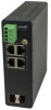
SISTP10x0-3xx-LRT Quick Start Guide SISTP10x0-3xx-LRT Series Industrial Unmanaged PoE/PoE+ GbE Switches Quick Start Guide The SISTP10x0-3xx-LRT series industrial unmanaged GbE switches are a plug-and-play Ethernet switches that make an easy transition to Gigabit Ethernet. The series includes two PoE+ models: SISTP1040-342-LRT and SISTP1040-382-LRT. Note: See the Install Guide for Safety Warnings, Cautions, Ordering info, features, specs, front/back panels, installation, grounding, power supply, LEDs, troubleshooting, regulatory agency, warranty, and contact information. Front Panel The SISTP1040-382-LRT front panel is shown right. RESET Button You can press the bottom panel RESET button to reboot the switch. Installation and Setup See the Install Guide for unpacking and package contents. The Switch can be Wall mounted or installed on a DIN Rail. See the Install Guide. Mounting the Switch on a Wall (Optional) 1. Attach the wall mounting plates to rear panel of chassis. Insert screws and tighten. 2. Install user-supplied screws on the appropriate location on the wall. 3. Make sure the switch is attached securely to wall. Mounting the Switch on a DIN Rail 1. Attach the DIN Rail mounting kit to the rear panel of the chassis. Insert screws and tighten. 2. Insert the upper lip of the DIN rail into the DIN-rail mounting kit and press switch towards DIN rail until it snaps into place. 3. Make sure that the switch is attached securely to DIN Rail. Note: Make all cable connections and perform grounding before connecting to power. Install and Connect SFPs via Fiber Optic Cable For SFP ports use UL Listed Optional Transceiver products, Rated 3.3Vdc, Laser Class 1. 1. Prepare a fiber optic cable with appropriate connecter. Warning: Fiber optic port is a Class 1 laser device. 2. Remove a rubber plug and position the SFP at an SFP slot with the label facing correctly. 3. Carefully slide the SFP device into the slot, aligning it with the internal installation guides. 4. Ensure that the SFP device is firmly seated against the internal mating connector. 5. See the related SFP manual for operating information specific to your particular SFP model. 6. Connect the other end of the cable to the appropriate far end Ethernet port. Note: After the cable is properly connected at both ends, the Switch LEDs should be functional. 33732 Rev. E https://www.lantronix.com/ Page 1 of 2
-
 1
1 -
 2
2
 |
 |
