Lantronix SLB Lantronix SLB V2007 - Quick Start Guide - Page 5
Connecting The Slb Continued, Installing The Slb
 |
View all Lantronix SLB manuals
Add to My Manuals
Save this manual to your list of manuals |
Page 5 highlights
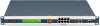
Quick Start Guide SLB Branch Office Manager CONNECTING THE SLB CONTINUED For example, to connect a PC to the device port of the SLB, you only need the female DB9 adapter (Part #200.2070A) and a standard Cat-5 cable, both of which are supplied with the SLB. CONSOLE & DEVICE PORT (RS-232) PIN ASSIGNMENTS The default communication parameters for the device ports and the console port are: • 9600 baud • 8 data bits • No parity • 1 stop bit • No flow control The power outlets allow your equipment to use the SLB as its power source. Once connected you can remotely and securely control the state of each outlet (on/off/reboot). 6 INSTALLING THE SLB 1. Install the unit in a 19-inch rack if desirable. Warning: Be careful not to block the air vents on the sides of the unit. If you mount it in an enclosed rack, we recommend that the rack have a ventilation fan. 2. Connect the SLB directly to the network through the top Ethernet port #1 or route through the integrated 8-port Ethernet switch (see connection diagram and instructions on page 4). 3. Connect up to eight serial console devices to the numbered device ports on the back of the unit using the appropriate cables and adapters. 4. To manage a device's power, plug its power cord into one of the four power outlets. 5. Install any PC cards you intend to use (optional). If you install a modem card, connect it to the phone line. 6. Attach the supplied power cord to the AC input connector and apply power. 7. Wait about a minute and a half for the boot process to end. When the boot process ends, the status of each power outlet displays on the LCD display. Detected faults or process messages may also display. WWW.LANTRONIX.COM 7
-
 1
1 -
 2
2 -
 3
3 -
 4
4 -
 5
5 -
 6
6 -
 7
7 -
 8
8
 |
 |
