Lantronix SLC 8000 Advanced Console Manager G520 LTE Connectivity Kit QSG - Page 1
Lantronix SLC 8000 Advanced Console Manager Manual
 |
View all Lantronix SLC 8000 Advanced Console Manager manuals
Add to My Manuals
Save this manual to your list of manuals |
Page 1 highlights
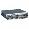
G520 LTE Connectivity Kit Quick Start Guide WHAT'S IN THE BOX G520 Series (G526GP1AS1) AC Power Supply 1. HARDWARE OVERVIEW Front View LEDs Ethernet (LAN, WAN/LAN #2) Antenna RJ45 to RJ45 CAT5 Back View SIM 2 SIM 1 Wi-Fi DC input Wi-Fi /Bluetooth *No RS-485 serial port available Cellular diversity GNSS Cellular main The Ethernet connection will be used to attach to your SLC 8000 Console Manager or SLB Branch Office Manager. 2. INSTALLING THE SIM CARD(S) & ANTENNA NOTE: For full information on G520 series gateway setup, see the G520 Quick Start Guide. 1 Remove the SIM card from its packaging. Locate the SIM 1 slot on the unit. To insert the SIM card, slide the latch for SIM 1 slot to the left and gently push the SIM card (contact side down) all the way into the slot. Release the latch. Note: The SIM card is pre-activated by Lantronix, but the APN may need to be configured in the software. See Quick Setup. 2 Attach the cellular / GNSS antenna to the antenna connectors. Connect the power cord to the power supply. Attach 3 the 3-pin plug on the power cord to the DC input on the unit. Connect the AC plug on the power supply to a standard AC receptacle. 4 Observe that the Power LED is lit. 5 The Lantronix G520 series (G52x) gateway must be configured before it can be used as the fail-over gateway. The default admin user password must be changed to a new password, and the DHCP server must be disabled. Please see G520 User Guide for more information on how to change the password. LEDs Alert Red User Blue Programmable 1 User Blue Programmable 2 Device alerts So ware configurable So ware configurable Ac vity Amber Cellular data ac vity Network Amber Cellular network status Signal Amber Cellular signal strength SIM Blue SIM in use Wi-Fi Blue Wi-Fi network status Power Green Power On or Off
-
 1
1 -
 2
2
 |
 |
