Lantronix TN-SFP-GE-x-C Series Various SFPs 33480 User Guide Rev D - Page 8
SFP Unpacking, SFP Installation, Cautions
 |
View all Lantronix TN-SFP-GE-x-C Series manuals
Add to My Manuals
Save this manual to your list of manuals |
Page 8 highlights
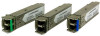
Lantronix TN-SFP-xxx User Guide SFP Unpacking Before you start installing the TN-SFP-xxx, verify that the package contains the following items: o One TN-10G-SFP-xxx o Two protective foam pieces o One Documentation Postcard Please notify your sales representative immediately if any of the above items is missing or damaged. Save the packaging for possible future use. SFP Installation The optical ports of the SFP transceiver must be terminated with an optical connector or with a dust plug. The SFP transceiver must be operated within the specified temperature and voltage limits. The Fiber Optic Association, Inc. provides a Technical Bulletin on "Guidelines for Testing and Troubleshooting Fiber Optic Installations" at http://www.thefoa.org/tech/guides/TT3.pdf. There are other FOA Technical Bulletins that should be used as references for the design and planning of the network. These documents can be downloaded from the FOA Tech Topics website. Cautions • The SFP tranceiver module is keyed to only be installed one way. However, if forced the wrong way, damage may occur. • Avoid getting dust or other contaminants into the fiber bore of the SFP transceiver module, as this will cause the optics to not operate properly. • Clean the optic surfacees of the optical fiber before you plug them back in to the optical bores of another SFP tranceiver module. • Each port must match the wavelength specifications on the other end of the cable, and the cable must not exceed the specified cable length for reliable communications. 33480 Rev. D http://www.lantronix.com/ 8
-
 1
1 -
2
-
 3
3 -
 4
4 -
 5
5 -
 6
6 -
 7
7 -
 8
8 -
 9
9 -
 10
10 -
 11
11 -
 12
12 -
 13
13 -
14
-
15
-
16
-
17
-
18
 |
 |
