Lantronix UDS2100 UDS2100 - Quick Start Guide - Page 6
Con The Uds2100, Led Troubleshooting, Contact - diagnostics
 |
View all Lantronix UDS2100 manuals
Add to My Manuals
Save this manual to your list of manuals |
Page 6 highlights
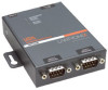
Quick Start Guide UDS2100 CONFIGURE THE UDS2100 Once the UDS2100 is in the device list, it can be configured. 1. Double-click the unit in the list. Details about the unit display. 2. Select one of the following tabs: Note: For details about configuration settings, see the UDS2100 User Guide. LED TROUBLESHOOTING The following LEDs are on the top of the UDS2100: ‹ Power / Diagnostic (Blue) ‹ RX Serial 1 Activity LED (Green) ‹ TX Serial 1 Activity LED (Yellow) ‹ RX Serial 2 Activity LED (Green) ‹ TX Serial 2 Activity LED (Yellow) The following LEDs are on the RJ45 Ethernet connector: ‹ Ethernet Link LED on the left (Bi-color, 10Mbps = Yellow, 100 Mbps = Green) ‹ Ethernet Activities LED on the right (Bi-color, Half Duplex = Yellow, Full Duplex = Green) 8 LEDS Power/Diagnostic (Blue) RX Serial 1 Activity LED (Green) TX Serial 1 Activity LED (Yellow) RX Serial 2 Activity LED (Green) TX Serial 2 Activity LED (Yellow) Ethernet Link LED on the left (Bi-color) Ethernet Activity LED on the right (Bi-color) MEANING Steady On = Power OK Blinking 2x = No DHCP response Blinking 2x = Setup Menu active Off = No data activity Blinking = Data being received by UDS2100 on channel 1 Off = No data activity Blinking = Data being transmitted from UDS2100 on channel 1 Off = No data activity Blinking = Data being received by UDS2100 on channel 2 Off = No data activity Blinking = Data being transmitted from UDS2100 on channel 2 Off = No Ethernet link established Solid Yellow = 10Mbps Ethernet link established Solid Green = 100 Mbps Ethernet Link established Off = No data activity Blinking Yellow = Half Duplex data activity Blinking Green = Full Duplex data activity CONTACT For questions and technical support, please check our online knowledge base at www.lantronix.com/support Lantronix 15353 Barranca Parkway, Irvine, CA 92618, USA Phone: (949) 453-3990 or Fax: (949) 453-3995 www.lantronix.com WWW.LANTRONIX.COM 9
-
 1
1 -
 2
2 -
 3
3 -
 4
4 -
 5
5 -
 6
6
 |
 |
