Lantronix XPress-DR-IAP XPress-DR / XPress-DR-IAP - Quick Start Guide
Lantronix XPress-DR-IAP Manual
 |
View all Lantronix XPress-DR-IAP manuals
Add to My Manuals
Save this manual to your list of manuals |
Lantronix XPress-DR-IAP manual content summary:
- Lantronix XPress-DR-IAP | XPress-DR / XPress-DR-IAP - Quick Start Guide - Page 1
Lantronix family of Device Servers. DSTni-XPress DR-IAP devices allow you to install the protocol suitable for your automation application. When you complete the setup, you can Ethernet-enable a serial device by connecting it to the serial port. (See the DSTni-XPress DR User Guide on the software - Lantronix XPress-DR-IAP | XPress-DR / XPress-DR-IAP - Quick Start Guide - Page 2
. See the user manual for troubleshooting network problems. 2. From the Ping Device window, you can ping devices not listed in the main window by entering a new address in the IP address field. DSTni-XPress DR-IAP devices allow you to install a protocol such as MODBUS Bridge for your automation
-
 1
1 -
 2
2
 |
 |

900-289 Rev B
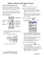
DSTni-XPress DR Quick Start
DSTni-XPress DR/DR-IAP
DSTni-XPress DR
and DSTni-XPress DR-IAP are
members of the Lantronix
family of Device Servers.
DSTni-XPress DR-IAP devices allow you to install the
protocol suitable for your automation application.
When you complete the setup, you can Ethernet-enable a
serial device by connecting it to the serial port.
(See the
DSTni-XPress DR User Guide on the software CD.)
Quick Connect
Screw Terminals for
RS-232 and RS-485/422
RJ45 Serial Port
RS-232 & RS-422/485
RS-232 or RS-485/422
Select Switch
Screw Terminals for
9-30VDC or 9-24VAC
RJ45 10/100BASE-T
Ethernet Port
Status LEDs
Reset Switch
Transmit Active LED
& Receive Active LED
RESET
10/100BASE-T
SERIAL
RS232
RS485
F
R
A
L
Ethernet
Serial
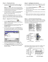
1.
Connect the XPress DR to the network through the
Ethernet port.
(The unit must be on the same network
as your computer.)
2.
Connect power (9-30VDC or 9-24VAC).
19
20
21
22
GND
GND
9-30VDC
DC+
DC-
9-24VAC
3.
Verify that the green Link LED is lit.
Setup
Follow these steps to quickly setup the device.
Step 1:
Start DeviceInstaller
1.
Insert the software CD into your CD-ROM drive.
When the main window appears, click the Device
Installer button and follow the instructions on the
screen.
2.
Click the Start button, and then point to Programs.
Point to the folder that contains Device Installer, then
click Device Installer. The Device Installer main
window will appear.
Step 2:
Assign an IP Address
1.
Click the
Assign IP
icon.
The Assign IP
Address window displays.
2.
In the
Enter the Hardware or Ethernet Address
field
, type the Ethernet address (MAC address) listed
on the Device Server label (on the right side of the
unit).
3.
In the
Enter IP Address to assign
field, type the IP
address of the Device Server (xxx.xxx.xxx.xxx
format). Select a
PC Network Class
.
4.
Click the
Set IP Address
button. The
Assign IP
Successful
message displays. Click
OK
.
Step 3:
Search the Network
1.
Click the
Search Network
icon
. The Search
Network window displays.
2.
Click the
Start Search
button. The message
Response
from xxx.xxx.xxx.xxx
appears in the window. Click the
Save
button and a device saved message appears. Click
OK
then the
Back
button. The IP Address and
Hardware Address appear in the window.