Lantronix xPico Wi-Fi Embedded Wi-Fi Module User Guide - Page 9
Serial Port 1, Antenna Port, Position, Label, Function, Default, xPico Wi-Fi Pin, Arduino Pin, JP3
 |
View all Lantronix xPico Wi-Fi Embedded Wi-Fi Module manuals
Add to My Manuals
Save this manual to your list of manuals |
Page 9 highlights
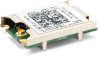
2: xPico Wi-Fi Shield JP JP11 Position Label 1-2 GND Function Board signal ground. Default Not installed J3, J1, J6, J2, ICSP1 J4, J5, Analog1, Power1, Connectors to mate to Arduino computer board. See schematic below. Test point through hole pads for Arduino computer board mating connectors. See schematic below. Serial Port 1 Serial port 1 of the xPico Wi-Fi embedded device server has the signals TXD1, RXD1. These signals are connected to the serial port on the Arduino computer board. Jumpers JP3 through JP5 allow you to change whether the xPico Wi-Fi module is DTE or DCE. If the xPico Wi-Fi module is connected to an MCU board, the jumpers should be connected 2-3. The RTS1 and CTS1 signals connect to header JP2, but do not connect to the Arduino computer board. xPico Wi-Fi Pin RXD1 (7) TXD1 (10) Arduino Pin JP3,JP5: 2-3 TX1 (J1 pin 2) RX1 (J1 pin 1) Arduino Pin JP3,JP5:1-2 RX1 (J1 pin 1) TX1 (J1 pin 2) Serial Port 2 Serial port 2 of the xPico Wi-Fi device has the signals TXD2 and RXD2. These signals go through jumpers JP17 pins 5 to 6 and 7 to 8. If the jumpers are installed the serial port is routed to an onboard USB to serial converter, which then connects to USB connector J9 on the board. In order to access the unit through the J9 USB port, you will need to install the USB-to-serial VCP driver from FTDI on your PC. It is available in the installation directory of the Lantronix® DeviceInstaller™ utility, 4.3.0.2 and later versions, for installation. It can also be obtained from the FTDI website provided below. Once installed, you will be able to view the xPico boot messages as well as provide command inputs through any PC terminal program, such as Tera Term. Download FTDI USB-to-serial drivers at this website: http://www.ftdichip.com/Drivers/VCP.htm Antenna Port The xPico Wi-Fi Shield includes a bracket for mounting the U.FL to reverse polarity SMA RF cable included with the kit. Follow the procedure below when installing the antenna cable. w Connect the U.FL cable to the module w Place the plastic retaining clip over the module w Install the module into the socket. w Install the external antenna to the SMA end of the RF cable. Note: Install or remove the module and antenna connections only while the module is powered off. xPico® Wi-Fi® Shield User Guide 9
-
 1
1 -
2
-
3
-
 4
4 -
 5
5 -
 6
6 -
 7
7 -
 8
8 -
 9
9 -
 10
10 -
 11
11 -
 12
12 -
 13
13 -
 14
14 -
15
-
16
-
17
 |
 |
