Lantronix xPico Wi-Fi Embedded Wi-Fi Module Application Note - Page 3
Lab Setup, Jumper Settings, Sample Programs for Using the Lantronix® xPico® Wi-Fi® Shield
 |
View all Lantronix xPico Wi-Fi Embedded Wi-Fi Module manuals
Add to My Manuals
Save this manual to your list of manuals |
Page 3 highlights
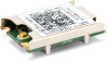
Lab Setup The following labs provide examples on how to use the xPico® Wi-Fi® Shield to connect an xPico Wi-Fi embedded device server to an Arduino® micro-computer board. These examples use Arduino Uno, however other Arduino platforms may be utilized. The firmware may change slightly. Prior to running the labs, download and install the open-source Arduino IDE from the Arduino website: http://arduino.cc/en/Main/Software#.UwYZNvldVKY In order to be able to create a virtual com port from a USB port it is also recommended that you install or update FTDI drivers on your personal computer from this website: http://www.ftdichip.com/Drivers/VCP.htm Jumper Settings This example does not require changing or modifying the xPico Wi-Fi Shield jumpers from their default settings. The default jumper settings for the xPico Wi-Fi Shield are described in Table 1 below. For more information about these jumpers, refer to the xPico Wi-Fi Shield User Guide (part number 900-709-R). Table 1 Jumper Settings JP: Position Position Label Function JP17: 1-2 Installed WLAN LED Install to use WLAN LED JP17 : 3-4 Installed WAKE Install to use wake-up input and button,SW1 JP17: 5-6 Installed RXD2 Install to route xPico Wi-Fi module second serial port to J9 via the on board USB to serial converter JP17: 7-8 Installed TXD2 Install to route xPico Wi-Fi module second serial port to J9 via the on board USB to serial converter JP17: 9-10 Installed DEFAULTS Install to use Defaults input and button, SW2 JP17: 11-12 JP3: 2-3 Installed RESET Installed TX JP5: 2-3 Installed RX JP2 1-2 JP2 3-4 JP2 5-6 JP2: 7-8 Installed CP1 Installed CP2 Installed CP3 Installed CP4 Install to use Hardware Reset input and button, SW3 Install position 2-3 to connect xPico module TXD1 to Arduino computer board serial RX. Install position 1-2 to connect xPico module RXD1 to Arduino computer board serial RX. Install position 2-3 to connect xPico module RXD1 to Arduino computer board serial TX. Install position 1-2 to connect xPico module TXD1 to Arduino computer board serial TX. Breakout header for CP1, pin 2 does not connect anywhere else on the board. Breakout header for CP2 Breakout header for CP3 Breakout header for CP4 Sample Programs for Using the Lantronix® xPico® Wi-Fi® Shield 3
-
 1
1 -
 2
2 -
 3
3 -
 4
4 -
 5
5 -
 6
6 -
 7
7 -
 8
8 -
 9
9
 |
 |
