Lantronix xPico Wi-Fi xPico Wi-Fi Freescale Tower System Module - Quick Start - Page 1
Lantronix xPico Wi-Fi Manual
 |
View all Lantronix xPico Wi-Fi manuals
Add to My Manuals
Save this manual to your list of manuals |
Page 1 highlights
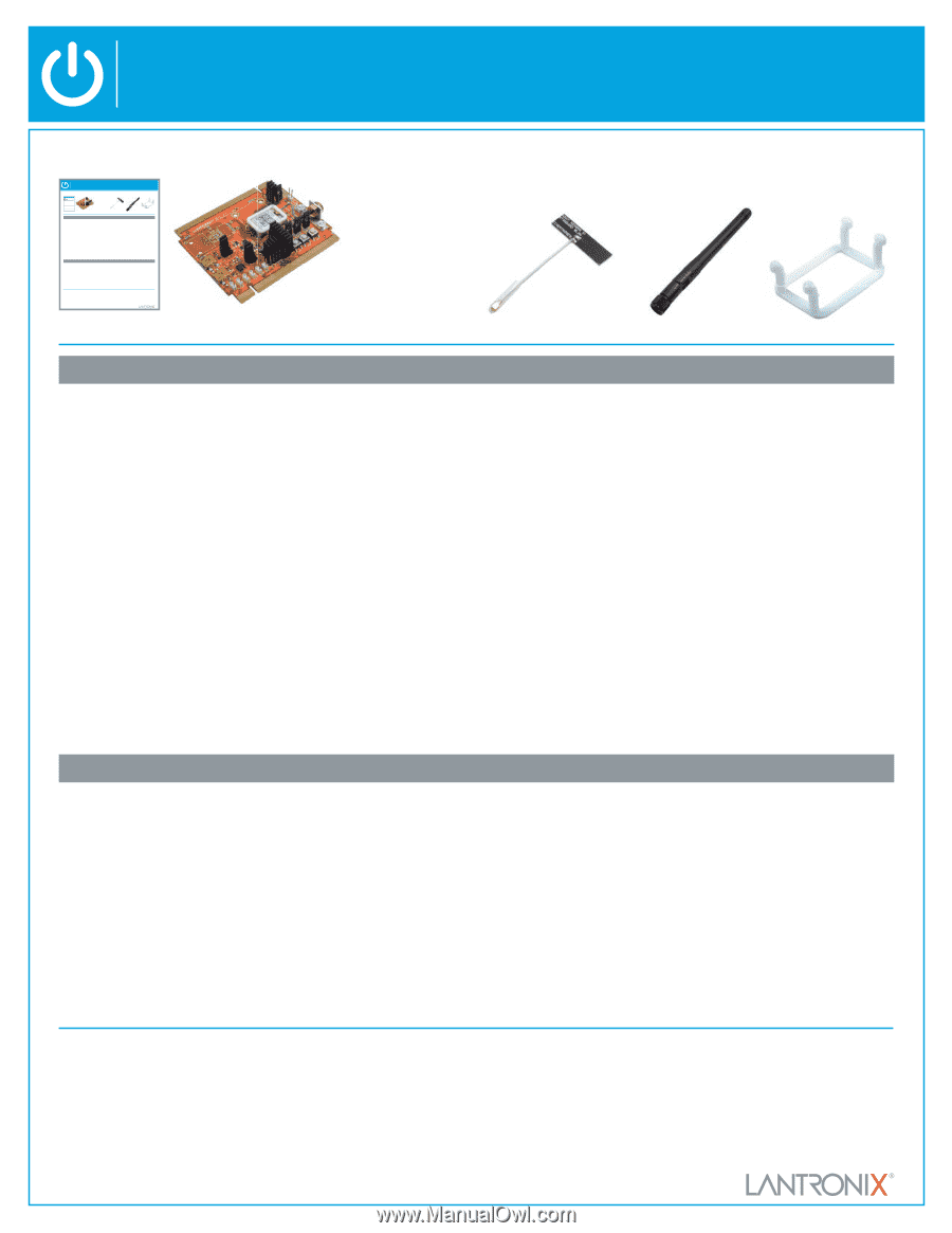
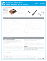
Lantronix® xPico® Wi-Fi® Freescale Tower System Module Quick Start Guide WHAT'S IN THE BOX Lantronix® xPico® Wi-Fi® Freescale Tower System Module Quick Start Guide WHAT'S IN THE BOX Lantronix® xPico® Wi-Fi® Freescale Tower System Module WHAT'S IN THE BOX xPico Wi-Fi Freescale Tower System Module Pre-installed with: • xPico Wi-Fi module • u.FL to R-SMA cable • xPico quick clip PCB Strip Antenna Quick Start Guide Antenna Additional xPico Quick Clip Quick Start Guide 1 INITIAL SETUP 1. Install the Lantronix® xPico® Wi-Fi® Freescale Tower System Module into the Elevator boards of the Tower System. 2. On another level, install either a TWR-SER serial board, or a Freescale processor module. Quick Start Guide 3. For Serial Port 1 operation, set the jumpers JP16 through JP19 in the correct position. Note that Serial Port 1 is always routed to serial port 1 on the Tower System: • For use with TWR-SER, set them to 1-2 • For use with MCU board, set them to 2-3 4. For Serial Port 2 operation, set the jumpers JP10 and JP11: • For routing to serial port 0 on Tower System, and use with an MCU board, set to 1-2 • For routing to on-board FTDI USB to serial converter and to J3 USB connector, set to 2-3 5. For USB device port operation (available in future firmware release), set the jumpers JP5 and JP7. 6. For routing to J2 connector, set to 2-3. 7. Connect the power supply. The board can be powered either by the on-board power regulator that draws power from the J3 USB connector, or from the Tower System. If both are connected, the board will draw power from the Tower System. 8. By default the SoftAP mode is enabled with a default SSID of XpicoWiFi_xxxxxx. Where xxxxxx are the last six characters of the unique xPico Wi-Fi serial number. This number is available on the module label. For example if the serial number on label were 0080A398010E then the SSID would be XpicoWiFi_98010E. 9. Connect your device to the SSID detailed above. The default security for the xPico Wi-Fi SoftAP is WPA2 and the passphrase is XPICOWIFI. 10. Open a web browser and navigate to either xpicowifi.lantronix.com or 192.168.0.1. 11. When prompted enter the USERNAME = admin and the PASSWORD = PASSWORD to access the Configuration and Management web pages. (Both are case sensitive). 2 CONFIGURATION CONNECT TO INFRASTRUCTURE NETWORK Once you can enter the Configuration and Management Web pages via the SoftAP interface by following the previous steps, you can configure the xPico Wi-Fi module's Client interface to connect to another Infrastructure network. On the Web pages, click the QuickConnect link on the navigation bar on the left hand side. The xPico Wi-Fi will scan for available networks. Click on the desired Access Point profile, enter the password when prompted, then click Submit to save to the xPico Wi-Fi module's configuration. The xPico Wi-Fi will connect to the infrastructure network and automatically obtain an IP address via DHCP. MANUAL SETUP If you would like to configure the xPico Wi-Fi to connect to a network that is not currently available, you can manually setup the network in the WLAN Profiles menu. Refer to the xPico Wi-Fi User's Guide for details. IP ADDRESS The Status page will display current information about the xPico Wi-Fi. You can view the IP address that was obtained from the DHCP server on the Client connection under the wlan0 interface. Contact Technical Support For technical support queries, visit http://www.lantronix.com/support or call (800) 422-7044 Monday - Friday from 6:00 a.m. - 5:00 p.m., Pacific Time, excluding holidays. Latest Firmware For the latest firmware downloads, visit http://www.lantronix.com/support/downloads IP Address Assignment Tutorial To view a tutorial on how to assign an IP address, visit http://www.lantronix.com/support/tutorials © Lantronix, Inc. 2013. All rights reserved. Lantronix and xPico are registered trademarks of Lantronix, Inc. in the U.S. and certain other countries. Wi-Fi is a registered trademark of Wi-Fi Alliance Corporation. Freescale is a registered trademark and Tower is a trademark of Freescale Semiconductor, Inc. All other trademarks and trade names are the property of their respective owners. 900-700-R Rev A Quick Start Guide xPico Wi-Fi Freescale Tower System Module Pre-installed with: • xPico Wi-Fi module • u.FL to R-SMA cable • xPico quick clip PCB Strip Antenna Antenna Additional xPico Quick Clip 1 INITIAL SETUP 1. Install the Lantronix® xPico® Wi-Fi® Freescale Tower System Module into the Elevator boards of the Tower System. 2. On another level, install either a TWR-SER serial board, or a Freescale processor module. Quick Start Guide 3. For Serial Port 1 operation, set the jumpers JP16 through JP19 in the correct position. Note that Serial Port 1 is always routed to serial port 1 on the Tower System: • For use with TWR-SER, set them to 1-2 • For use with MCU board, set them to 2-3 4. For Serial Port 2 operation, set the jumpers JP10 and JP11: • For routing to serial port 0 on Tower System, and use with an MCU board, set to 1-2 • For routing to on-board FTDI USB to serial converter and to J3 USB connector, set to 2-3 5. For USB device port operation (available in future firmware release), set the jumpers JP5 and JP7. 6. For routing to J2 connector, set to 2-3. 7. Connect the power supply. The board can be powered either by the on-board power regulator that draws power from the J3 USB connector, or from the Tower System. If both are connected, the board will draw power from the Tower System. 8. By default the SoftAP mode is enabled with a default SSID of XpicoWiFi_xxxxxx. Where xxxxxx are the last six characters of the unique xPico Wi-Fi serial number. This number is available on the module label. For example if the serial number on label were 0080A398010E then the SSID would be XpicoWiFi_98010E. 9. Connect your device to the SSID detailed above. The default security for the xPico Wi-Fi SoftAP is WPA2 and the passphrase is XPICOWIFI. 10. Open a web browser and navigate to either xpicowifi.lantronix.com or 192.168.0.1. 11. When prompted enter the USERNAME = admin and the PASSWORD = PASSWORD to access the Configuration and Management web pages. (Both are case sensitive). 2 CONFIGURATION CONNECT TO INFRASTRUCTURE NETWORK Once you can enter the Configuration and Management Web pages via the SoftAP interface by following the previous steps, you can configure the xPico Wi-Fi module's Client interface to connect to another Infrastructure network. On the Web pages, click the QuickConnect link on the navigation bar on the left hand side. The xPico Wi-Fi will scan for available networks. Click on the desired Access Point profile, enter the password when prompted, then click Submit to save to the xPico Wi-Fi module's configuration. The xPico Wi-Fi will connect to the infrastructure network and automatically obtain an IP address via DHCP. MANUAL SETUP If you would like to configure the xPico Wi-Fi to connect to a network that is not currently available, you can manually setup the network in the WLAN Profiles menu. Refer to the xPico Wi-Fi User's Guide for details. IP ADDRESS The Status page will display current information about the xPico Wi-Fi. You can view the IP address that was obtained from the DHCP server on the Client connection under the wlan0 interface. Contact Technical Support For technical support queries, visit http://www.lantronix.com/support or call (800) 422-7044 Monday - Friday from 6:00 a.m. - 5:00 p.m., Pacific Time, excluding holidays. Latest Firmware For the latest firmware downloads, visit http://www.lantronix.com/support/downloads IP Address Assignment Tutorial To view a tutorial on how to assign an IP address, visit http://www.lantronix.com/support/tutorials © Lantronix, Inc. 2013. All rights reserved. Lantronix and xPico are registered trademarks of Lantronix, Inc. in the U.S. and certain other countries. Wi-Fi is a registered trademark of Wi-Fi Alliance Corporation. Freescale is a registered trademark and Tower is a trademark of Freescale Semiconductor, Inc. All other trademarks and trade names are the property of their respective owners. 900-700-R Rev A Quick Start Guide xPico Wi-Fi Freescale Tower System Module Pre-installed with: • xPico Wi-Fi module • u.FL to R-SMA cable • xPico quick clip PCB Strip Antenna Antenna Additional xPico Quick Clip 1 INITIAL SETUP 1. Install the Lantronix® xPico® Wi-Fi® Freescale Tower System Module into the Elevator boards of the Tower System. 2. On another level, install either a TWR-SER serial board, or a Freescale processor module. Quick Start Guide 3. For Serial Port 1 operation, set the jumpers JP16 through JP19 in the correct position. Note that Serial Port 1 is always routed to serial port 1 on the Tower System: • For use with TWR-SER, set them to 1-2 • For use with MCU board, set them to 2-3 4. For Serial Port 2 operation, set the jumpers JP10 and JP11: • For routing to serial port 0 on Tower System, and use with an MCU board, set to 1-2 • For routing to on-board FTDI USB to serial converter and to J3 USB connector, set to 2-3 5. For USB device port operation (available in future firmware release), set the jumpers JP5 and JP7. 6. For routing to J2 connector, set to 2-3. 7. Connect the power supply. The board can be powered either by the on-board power regulator that draws power from the J3 USB connector, or from the Tower System. If both are connected, the board will draw power from the Tower System. 8. By default the SoftAP mode is enabled with a default SSID of XpicoWiFi_xxxxxx. Where xxxxxx are the last six characters of the unique xPico Wi-Fi serial number. This number is available on the module label. For example if the serial number on label were 0080A398010E then the SSID would be XpicoWiFi_98010E. 9. Connect your device to the SSID detailed above. The default security for the xPico Wi-Fi SoftAP is WPA2 and the passphrase is XPICOWIFI. 10. Open a web browser and navigate to either xpicowifi.lantronix.com or 192.168.0.1. 11. When prompted enter the USERNAME = admin and the PASSWORD = PASSWORD to access the Configuration and Management web pages. (Both are case sensitive). 2 CONFIGURATION CONNECT TO INFRASTRUCTURE NETWORK Once you can enter the Configuration and Management web pages via the SoftAP interface by following the previous steps, you can configure the xPico Wi-Fi module's client interface to connect to another infrastructure network. On the web pages, click the QuickConnect link on the navigation bar on the left hand side. The xPico Wi-Fi will scan for available networks. Click on the desired Access Point profile, enter the password when prompted, then click Submit to save to the xPico Wi-Fi module's configuration. The xPico Wi-Fi will connect to the infrastructure network and automatically obtain an IP address via DHCP. MANUAL SETUP If you would like to configure the xPico Wi-Fi to connect to a network that is not currently available, you can manually setup the network in the WLAN Profiles menu. Refer to the xPico Wi-Fi User's Guide for details. IP ADDRESS The Status page will display current information about the xPico Wi-Fi. You can view the IP address that was obtained from the DHCP server on the client connection under the wlan0 interface. Contact Technical Support For technical support queries, visit http://www.lantronix.com/support or call (800) 422-7044 Monday - Friday from 6:00 a.m. - 5:00 p.m., Pacific Time, excluding holidays. Latest Firmware For the latest firmware downloads, visit http://www.lantronix.com/support/downloads IP Address Assignment Tutorial To view a tutorial on how to assign an IP address, visit http://www.lantronix.com/support/tutorials © Lantronix, Inc. 2013. All rights reserved. Lantronix and xPico are registered trademarks of Lantronix, Inc. in the U.S. and certain other countries. Wi-Fi is a registered trademark of Wi-Fi Alliance Corporation. Freescale is a registered trademark and Tower is a trademark of Freescale Semiconductor, Inc. All other trademarks and trade names are the property of their respective owners. 900-700-R Rev A
-
 1
1
 |
 |