Lasko 2535 User Manual - Page 4
Model 2535, Modelo 2535
 |
View all Lasko 2535 manuals
Add to My Manuals
Save this manual to your list of manuals |
Page 4 highlights
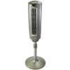
MODEL 2535 OPERATION This Fan may be operated by the Manual Controls located on top of the unit (as shown in Figure 5) or by the Remote Control (shown in Figure 6). 1. Place the Fan on a firm and level surface. 2. Plug the cord set into a 120 volt outlet. Be sure that the plug fits tightly into outlet. When plugs fit loosely into receptacles, they may slip partially or completely out of the receptacle with only the slight movement of the attached cord. Receptacles in this condition may overheat and pose a serious fire hazard; if covered by a curtain or drape, the fire hazard is even greater. 3. Turn the Fan ON by pressing the Power Button ( ). 4. SPEEDS: Press the Fan Speed Button ( ) to desired speed setting. Each time the Fan Speed Button is pressed, the speed will change from Low (1), to Medium (2), to High (3). When intially plugged in, the Fan will be in Low Speed. When the Fan is turned OFF and ON again, the unit will resume the speed at which it was turned OFF. 5. OSCILLATION: Press the Oscillation Button ( ) to start and stop the oscillation function. 6. TIMER: The timer function allows the unit to be set to operate for a length of time from 1/2 hour to 7 1/2 hours, in increments of a 1/2 hour. Press the Timer Button ( ) to set the length of time desired. Each time the timer button is pressed, the time is increased by 1/2 hour. After reaching 7 1/2 hours, pressing the timer button once more will reset the Fan to continuous running. The lights on the front of the unit will light up appropriately with the length of time that the Fan is set for. 7. SLEEP: This function allows the unit to be set in Sleep Mode. Pressing the Sleep Button ( ) once will set the unit on Low for 6 continuous hours. Pressing the Sleep Button ( ) a second time will reset the unit to 6 continuous hours. The Oscillation Button ( ) will function when the Fan is in Sleep Mode. Pressing any other button (Timer, Fan Speed or the Power Button) will shut off the Sleep Mode. 8. To turn the Fan OFF, press the Power Button ( ) and unplug the unit from the electrical outlet. MODELO 2535 HERRAMIENTAS NECESARIAS PARA EL ARMADO (no incluida) - Destornillador de Cabeza Phillips # 2 ARMADO DE LA TUBERÍA (Figura 1) 1. Saque el conjunto de la tubería del cartón como muestra. (Paso 1) 2. Desafloje la Tuerca De Ajuste De Altura, girando en sentido contrahorario. (Paso 2) 3. Eleve la Extensión De La Tubería. (Paso 3) 4. Apriete la Tuerca De Ajuste De Altura, girando en sentido horario. (Paso 4) ENSAMBLE DEL PIE (Figura 3) COLOQUE LA BASE EN EL PISO 1. Utilizando un movimiento giratorio, inserte el extremo del tubo de diámetro grande en el agujero de la Base. El girar el tubería a medida que se lo empuja asegura que el tubería quede plenamente asentado en la base. 2. Para ajustar la altura: a) Afloje la Tuerca De Ajuste De Altura. b) Eleve o baje el Extensión De La Tubería hasta obtener la altura deseada. c) Apriete la Tuerca De Ajuste De Altura. Extensión De La Tubería Paso 1 Tuerca De Ajuste De Altura Paso 2 Conjunto del Cabezal Extensión De La Tubería Extensión De La Tubería Tuerca De Ajuste De Altura Tuerca De Ajuste De Altura Paso 3 Paso 4 Figura 1 Armado de la Base (Figura 2) 1. Arme la Base entrecerrando las Copas en los Orificios De Copa situados en la Parte Inferior De La Base. 2. Fije (5) Tornillos #8 X 1/2" en los Orificios De Copa en la Parte Inferior De La Base. PARTE INFERIOR DE LA BASE (5) Tornillos #8 X 1/2" Base Figura 3 CONJUNTO DE LA CABEZA (Figura 4) 1. Coloque el Conjunto del Cabezal sobre el extremo del Extensión De La Tubería torciendo Conjunto del Cabezal abajo hastaquese siente en el Extensión De La Tubería. (Figura 4) Rev. G 10/08 Figure 5 4 Orificios De Copa 2535ES Rev. G 10/08 Conjunto del Cabezal Copas Extensión De La Tubería Figura 2 9 Figura 4 2535ES
-
 1
1 -
 2
2 -
 3
3 -
 4
4 -
 5
5 -
 6
6
 |
 |
