Lasko 4443 User Manual - Page 4
Model 4443, Modelo 4443
 |
View all Lasko 4443 manuals
Add to My Manuals
Save this manual to your list of manuals |
Page 4 highlights
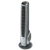
MODEL 4443 OPERATION (Figure 4) This Fan may be operated by the local controls located on top of the unit (as shown in Figure 4 or by the Remote Control (shown in Figure 5). 1. Place the Fan on a firm and level surface. CAUTION: Plastic or rubber tabs, like the feet on this unit, may stick to furniture surfaces and/or hardwood floors. The unit may leave a residue that could darken, stain or leave permanent blemishes on the finish of certain furniture surfaces, including wood surfaces, and/or hardwood floors. 2. Plug the cord set into a 120 V~ outlet. Be sure that the plug fits tightly into outlet. When plugs fit loosely into receptacles, they may slip partially or completely out of the receptacle with only the slight movement of the attached cord. Receptacles in this condition may overheat and pose a serious fire hazard; if covered by a curtain or drape, the fire hazard is even greater. 3. Turn on the Fan by pressing the Power Button ( ) on the unit or the remote control. 4. Speeds: Adjust the speed of the Fan by pressing the Fan Speed Button ( ) after the power is turned on. Each time the speed button is pressed, the speed will change, from High (3), to Medium (2), to Low (1). 5. Oscillation: With the Fan on, press the Oscillation Button ( ) to start and stop the oscillation function. The oscillation function can be used in any speed. 6. Nightlight: Press the Nightlight Button ( ) to turn on and off the light at the base of the Fan. The nightlight function will work when the Fan is ON or OFF. 7. To turn the Fan OFF, press the Power Button ( ) and unplug the unit from the electrical outlet. Night Light Button Oscillation Button Power Button Fan Speed Button Figure 4 MODELO 4443 HERRAMIENTAS NECESARIAS PARA EL ARMADO (no incluida) 4. Alinee la Montura de la Base de Apoyo con la Base del Motor, - Destornillador de Cabeza Phillips # 2 teniendo en cuenta que la ranura del cable en la parte inferior de la montura de la base de apoyo debe apuntar hacia la parte posterior del Ventilador. Adose la Montura de la Base ARMADO de Apoyo a la Base del Motor con (4) Tornillos Largos M5 de 1/2". Cerciórese de alinear la Llave del Conjunto de la Base 1. Para un armado más sencillo, deposite el Ventilador hacia abajo de Soporte con la Muesca Localizadora de la Base Del Motor. para que la parrilla frontal y el panel de control apunten hacia (Figura 1) Suavemente tire del Cable Eléctrico para evitar que arriba. quede flojo y colóquelo en el Orificio de Colocación del Cable. 2. Arme las Mitades de la Base de Apoyo encastrando las Puntas de (Figura 3) la Base de Apoyo A con los Orificios para Puntas en la Base de Apoyo B. Conecte el Cable Eléctrico a través del orificio grande en el centro de la Montura de la Base de Apoyo. (Figura 1) Puntas de la Base de Apoyo A Montura de la Base de Apoyo Puntas de la Base de Apoyo B Puntas Figura 1 3. Asegure (4) #8 X 1/2" Tornillos en los dos orificios externos en la parte inferior de la Base cuando mostrado. (Figura 2) Puntas de la Base de Apoyo B Tornillos Largos M5 de 1/2" Cable Eléctrico Orificio de Colocación del Cable Figura 3 Rev. A 10/10 4 4443ES Puntas de la Base de Apoyo A Rev. A 10/10 Figura 2 9 4443ES
-
 1
1 -
 2
2 -
 3
3 -
 4
4 -
 5
5 -
 6
6
 |
 |
