Lasko 6356 User Manual - Page 4
Model 6356, Modelo 6356
 |
View all Lasko 6356 manuals
Add to My Manuals
Save this manual to your list of manuals |
Page 4 highlights
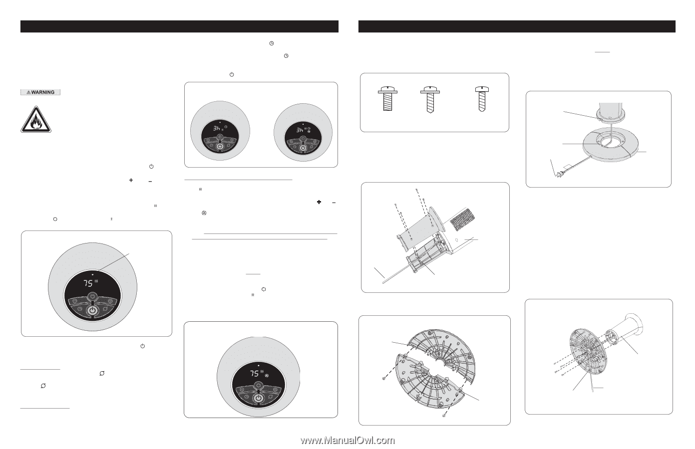
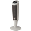
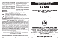
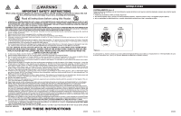
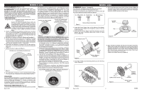
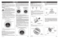
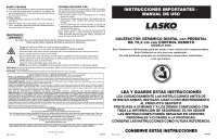
MODEL 6356 OPERATION (Figures 1 through 3) 1. Place the Heater on a firm, level surface, after assembling per these instructions. WARNING: Plastic or rubber tabs, like the feet on this unit, may stick to furniture surfaces and/or hardwood floors. The unit may leave a residue that could darken, stain or leave permanent blemishes on the finish of certain furniture surfaces, including wood surfaces, and/or hardwood floors. 2. Plug the cord set into a 120 volt outlet. Be sure that the plug fits tightly into outlet. When plugs fit loosely into receptacles, they may slip partially or completely out of the receptacle with only the slight movement of the attached cord. Receptacles in this condition may overheat and pose a serious fire hazard; if covered by a curtain or drape, the fire hazard is even greater. 3. When the Heater is initially plugged in, there will be a "beep" and the Power Light will come on indicating that there is power to the unit. The Power Light will remain lit until the Heater is unplugged from the electrical outlet. (Figure 1) 4. Turn the Heater ON by pressing the Power Button ( ). 5. When initially turned on, the Heater will display the current room temperature in ° Fahrenheit. Press the ( ) and ( ) buttons at the same time to change the display to ° Celsius. Press the same two buttons together again to change the display back to ° Fahrenheit. 6. Upon turning the Heater on, the unit will be in HIGH heat ( ) (1500 Watts) and will display the current room temperature. (Figure 1) 7. Press the ( ) button for LOW heat ( ). Display when initially turned on Power Light of time the Heater will run before turning itself off, from 1 hour to 8 hours. Pressing the Timer Button ( ) will increase the length of time by 1 hour each time this button is pressed. After the display reflects 8 hours, pressing the Timer Button ( ) once more will reset the Heater to run continuously. The Heater will turn off when the set time has elapsed. The unit can be turned back on by pressing the Power Button ( ). Timer Function in Low Heat Timer Function in High Heat and Automatic Temperature Control Figure 2 AUTOMATIC TEMPERATURE CONTROL (Figure 3) The automatic temperature function will only operate on "High" heat ( ). You cannot set the temperature automatically when the unit is in the low heat mode. 1. To set the room at a specific temperature press the ( ) or ( ) buttons to the desired temperature. The display will now reflect the ( ) and the temperature will be flashing. The Heater is now in Auto Temperature Mode. 2. When you reach the temperature at which you want to set the unit, the set temperature will flash several times and then the display will return to indicate the current room temperature and will gradually change as the room temperature changes. NOTE: the temperature display does not indicate the temperature of the heated air being emitted by the heater. 3. Once the room temperature reaches 2 degrees above the set temperature, the Heater will shut off. Once the room temperature reaches 1 degree below the set temperature, the Heater will turn back on and continue to cycle off and on to maintain the set temperature. 4. This function will cancel if the ( ) button is pressed. The Heater will now be in High heat ( ) and run continuously. NOTE: It is normal for the Heater "fan" to run for approximately 15 seconds when the Heater shuts off after reaching the set temperature. Figure 1 Display reflects High Heat and Automatic Temperature Control Function 8. To turn the Heater OFF, press the Power Button ( ) and unplug the Heater from the electrical outlet. OSCILLATION: Pressing the Oscillation Button ( ) will allow the Heater to oscillate back and forth. To stop the oscillation, press the Oscillation Button ( ) again. When the Heater is in Automatic Temperature Control, the oscillation function will stop when the set temperature is reached and resume when the Heater turns back on. TIMER FUNCTION (Figure 2) The timer function may be activated when the Heater display is in any function or speed. This function allows you to set the length Figure 3 Rev. A 2/10 4 6356ES MODELO 6356 ARMADO (Figuras 1 a 5) Herramientas Necesarias: Destornillador de Cabeza en cruz (no incluido) Retire cuidadosamente el Calefactor de su bolsa y caja. Para facilitar el armado, coloque el Calefactor de manera que la parrilla frontal y el panel de control den hacia abajo. 4. Fije las mitades de la base con (2) tornillos M4 X 13 mm. (Figura 3) Pase el Cable Eléctrico por el orificio grande que se encuentra en el Conjunto de la Base. NOTA: El Canal Para Cable en la parte inferior de la base debe estar hacia la parte posterior del Calefactor. (4) - M5 X 13mm (2) - M4 X 13mm (4) - M3.5 X 12mm Figura 1 Tamaño Real De Tornillos 1. Coloque el Cable Eléctrico en la parte inferior del Calefactor. Pase el Cable Eléctrico por el centro del Conjunto de Soporte de Columna. 2. Una el Conjunto de Soporte de Columna a la Base del Motor con (4) tornillos M3.5 x 12 mm. Cerciórese de que la Llave que está en la Base del Motor quede alineada con la Muesca de Ubicación en el Conjunto de Soporte de Columna. (Figura 2) (4) - M3.5 X 12mm Muesca de Ubicación Llave Cable Eléctrico Figura 4 Conjunto de la Base Base del Motor Cable Eléctrico Figura 2 Conjunto de Soporte de Columna 3. Arme la base enclavando las Protuberancias en los Orificios para Protuberancias. (Figura 3) 5. Alinee el Conjunto de la Base con el Conjunto de Soporte de Columna. Cerciórese de que la Muesca de Ubicación en el Conjunto de Soporte de Columna quede alineada con la Llave en el Conjunto de la Base (Figura 4). Una el Conjunto de la Base al Conjunto de Soporte de Columna con (4) tornillos M5 X 13 mm. Jale suavemente el Cable Eléctrico para que no quede holgado, y colóquelo en el Canal Para Cable del Conjunto de la Base. (Figura 5) (4) tornillos M5 X 13 mm Protuberancias Conjunto de Soporte de Columna Figura 3 Rev. A 2/10 Orificios para Protuberancias Canal Para Cable Figura 5 9 Cable Eléctrico 6356ES
-
 1
1 -
 2
2 -
 3
3 -
 4
4 -
 5
5 -
 6
6
 |
 |