Lasko S18602 User Manual - Page 3
OperaciÓn
 |
View all Lasko S18602 manuals
Add to My Manuals
Save this manual to your list of manuals |
Page 3 highlights
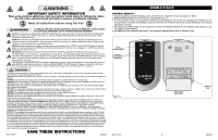
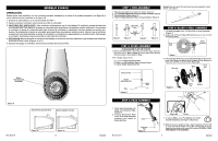
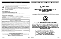
MODELO S18602 OPERACIÓN Puede operar este ventilador con los controles manuales ubicados en el frente de la unidad (mostrado en la Figura 9) o con el control remoto (mostrado en la Figura 12). 1. Conecte el cable eléctrico a un tomacorriente de 120 V~. 2. Aplique energía al ventilador presionando la perilla de velocidad. 3. VELOCIDAD DEL VENTILADOR: Este ventilador está equipado con 5 velocidades. El ventilador operará inicialmente en velocidad alta. Para disminuir el ajuste de velocidad, gire la perilla de velocidad en sentido antihorario. Una vez que el ventilador se ajusta a la velocidad más baja, el ajuste de velocidad no cambiará si se sigue girando en sentido antihorario. Para aumentar el ajuste de velocidad, gire la perilla de velocidad en sentido horario. Una vez que el ventilador se ajusta a la velocidad más alta, el ajuste de velocidad no cambiará si se sigue girando en sentido horario. Para apagar el ventilador, simplemente oprima la perilla de velocidad del ventilador. 4. OSCILACION: Empuje la perilla de oscilación hacia abajo en el estuche del motor para hacer que la cabeza del ventilador se mueva de lado a lado. (Figuras 10 y 11) 5. Después de apagar el ventilador, desconecte la unidad del tomacorriente. Botón Velocidad del Ventilador STEP 1: PIPE ASSEMBLY 1. Take pipe assembly out of carton as shown. (Figure 1) 2. Loosen Height Adjustment Nut turning counter clockwise. (Figure 2) 3. Raise Extension Pipe. (Figure 3) 4. Tighten Height Adjustment Nut turning clockwise. (Figure 4) Do Not take pipe apart. Should pipes become separated, insert pipe A into pipe B. B A Figure 1 Extension Pipe Height Adjustment Nut Figure 2 Figure 3 Figure 4 STEP 2: STAND ASSEMBLY PLACE BASE FLAT ON FLOOR 1. With a twisting motion, insert the end of the large diameter pipe into hole in Base. (Figure 5) Turning pipe while pushing will assure pipe is fully seated in Base. 2. For Height Adjustment: a) Loosen Height Adjustment Nut. b) Raise or lower Extension Pipe to desired height. c) Tighten Height Adjustment Nut. STEP 4: BLADE & GRILL ASSEMBLY 1. Tilt Head Assembly back. Put Rear Grill on Head Assembly. (Figure 7) 2. Align tab of Plastic Rear Grill with groove on top of front Head Assembly. Rear Grill Head Assembly Figure 7 3. Fully seat Rear Grill and secure with Plastic Nut turning Clockwise. Slide Blade onto Motor Shaft. (Figure 8) Align Groove on blade hub with Pin on motor shaft. (Figure 8A) Rear Grill Blade Front Grill Extension Pipe Height Adjustment Nut Base Figure 5 Larger Pipe Figure 8 Plastic Nut Fan Spinner Pin Figura 9 Hacia Arriba: Estacionario Hacia Adelante: Oscilar Rev. B 12/17 Figura 10 Figura 11 10 2084902 STEP 3: HEAD ASSEMBLY 1. Place Head Assembly with Collar onto Extension Pipe. (Figure 6) 2. Holding Extension Pipe firmly, twist Head Assembly downward until seated on Extension Pipe. Head Assembly Collar Rev. B 12/17 Extension Pipe Figure 6 Figure 8A Groove 4. To secure Blade, screw Fan Spinner onto Shaft Counter Clockwise until tight on Blade hub. 5. With fan head in upright position, align Ornament of Front Grill so it is horizontal and right side up. By starting with the top of the grill and working down, snap Grill in place. NO GRILL CLIPS ARE NEEDED FOR ASSEMBLY. 3 2084902
-
 1
1 -
 2
2 -
 3
3 -
 4
4 -
 5
5 -
 6
6
 |
 |
