Lenovo 8922A2U Hardware Maintenance Manual - Page 78
System, board, bottom, cover, assembly, cover
 |
UPC - 883609032302
View all Lenovo 8922A2U manuals
Add to My Manuals
Save this manual to your list of manuals |
Page 78 highlights
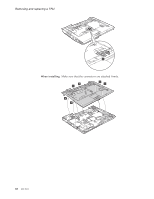
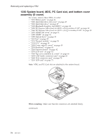
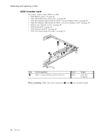
Removing and replacing a FRU 1230 System board, MDC, PC Card slot, and bottom cover assembly (D cover) For access, remove these FRUs, in order: v "1010 Battery pack" on page 46 v "1020 Hard disk drive slot cover" on page 47 v "1030 Hard disk drive" on page 47 v "1040 Bluetooth daughter card (BDC)" on page 48 v "1050 PCI Express Mini Card for 802.11 a/b/g wireless LAN" on page 49 v "1060 PCI Express Mini Card for 802.11 a/b/g/n wireless LAN" on page 50 v "1070 DIMM slot cover" on page 51 v "1080 DIMM" on page 52 v "1090 Optical drive" on page 53 v "1110 Fan" on page 55 v "1120 Thermal module" on page 56 v "1130 CPU" on page 58 v "1140 Cover, strip (E cover)" on page 59 v "1150 Keyboard" on page 60 v "1160 Function board" on page 62 v "1170 LCD unit" on page 63 v "1180 Top cover assembly (C cover)" on page 66 v "1190 USB/Audio connector card" on page 69 v "1200 VGA connector card" on page 70 v "1210 LED card" on page 71 Note: MDC and PC Card slot are attached to the system board. 1 When installing: Make sure that the connectors are attached firmly. (continued) 72 MT 8922
-
 1
1 -
2
-
3
-
4
-
5
-
6
-
7
-
8
-
9
-
10
-
11
-
12
-
13
-
14
-
15
-
16
-
17
-
18
-
19
-
20
-
21
-
22
-
23
-
24
-
25
-
26
-
27
-
28
-
29
-
30
-
31
-
32
-
33
-
34
-
35
-
36
-
37
-
38
-
39
-
40
-
41
-
42
-
43
-
44
-
45
-
46
-
47
-
48
-
49
-
50
-
51
-
52
-
53
-
54
-
55
-
56
-
57
-
58
-
59
-
60
-
61
-
62
-
63
-
64
-
65
-
66
-
67
-
68
-
69
-
70
-
71
-
72
-
 73
73 -
 74
74 -
 75
75 -
 76
76 -
 77
77 -
 78
78 -
 79
79 -
 80
80 -
 81
81 -
 82
82 -
 83
83 -
84
-
85
-
86
-
87
-
88
-
89
-
90
-
91
-
92
-
93
-
94
-
95
-
96
-
97
-
98
-
99
-
100
-
101
-
102
-
103
-
104
 |
 |
