Lenovo A700 Lenovo IdeaCentre A700 Hardware Maintenance Manual - Page 52
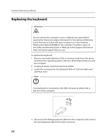
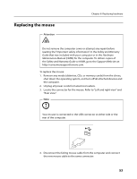
Replacing the camera
 |
View all Lenovo A700 manuals
Add to My Manuals
Save this manual to your list of manuals |
Page 52 highlights
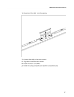
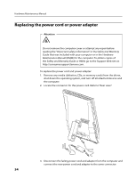
Hardware Maintenance Manual 19. Align then place the new LED panel into to chassis. 20. Connect the cables to the new LED panel, and screw in the new LED panel to the chassis. 21. Install all relative parts back. 22. Install the computer back cover and the computer stand. Replacing the camera To replace the camera 1. Remove the computer stand. Refer to "Removing the computer stand". 2. Remove the computer cover. Refer to "Removing the computer cover". 3. Remove the motherboard cover. Refer to "Removing the motherboard cover". 4. Remove the memory module. Refer to "Replacing a memory module". 5. Remove the connectors module. Refer to "Replacing the connectors module". 6. Remove the WLAN module. Refer to "Replacing the WLAN module" 7. Remove the system fans. Refer to "Replacing the system fans". 8. Remove the heatsink. Refer to "Replacing the heatsink". 9. Remove the speakers system. Refer to "Replacing the speakers systems". 10. Remove the hard disk drive. Refer to "Replacing the hard disk drive". 11. Remove the optical disk drive. Refer to "Replacing the optical disk drive". 12. Remove the inverter board. "Replacing the inverter board". 13. Remove the bluetooth module. Refer to "Replacing the bluetooth module". 14. Remove the touch module. Refer to "Replacing the touch module ". 15. Remove the motherboard. Refer to "Replacing the motherboard". 16. Remove the LED panel. Refer to "Replacing the LED panel". 17. Push the pins to release the camera cover. 18. Lift out the camera. 50
-
 1
1 -
2
-
3
-
4
-
5
-
6
-
7
-
8
-
9
-
10
-
11
-
12
-
13
-
14
-
15
-
16
-
17
-
18
-
19
-
20
-
21
-
22
-
23
-
24
-
25
-
26
-
27
-
28
-
29
-
30
-
31
-
32
-
33
-
34
-
35
-
36
-
37
-
38
-
39
-
40
-
41
-
42
-
43
-
44
-
45
-
46
-
 47
47 -
 48
48 -
 49
49 -
 50
50 -
 51
51 -
 52
52 -
 53
53 -
 54
54 -
 55
55 -
 56
56 -
 57
57 -
58
-
59
 |
 |
