Lenovo B40-30 Laptop Hardware Maintenance Manual - Lenovo B40-xx Notebook - Page 42
When installing, Screw quantity, Color, Torque, Removal, steps, drive, continued
 |
View all Lenovo B40-30 Laptop manuals
Add to My Manuals
Save this manual to your list of manuals |
Page 42 highlights
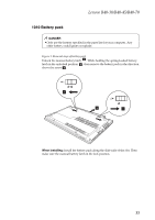
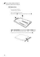
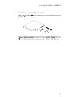
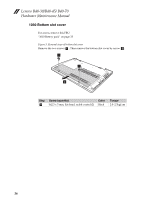
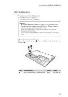
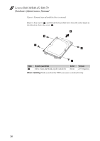
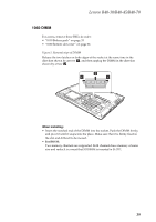
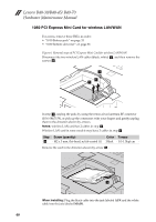
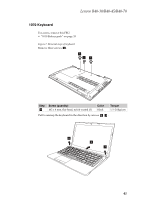
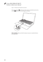
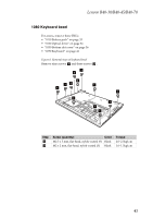
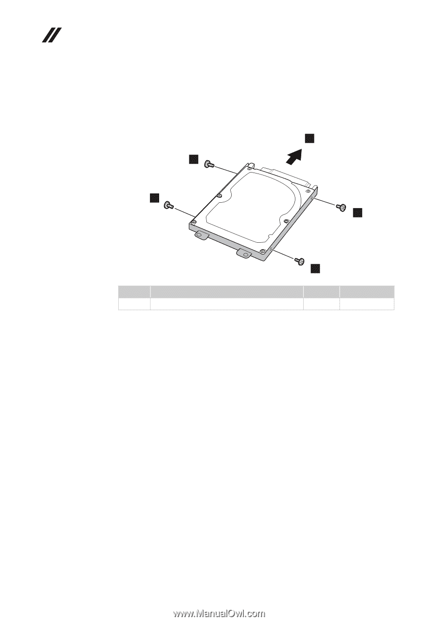
Lenovo B40-30/B40-45/ B40-70 Hardware Maintenance Manual Figure 4. Removal steps of hard disk drive (continued) Remove four screws e c and detach the hard disk drive from the metal frame in the direction shown by arrow e d . 4 3 3 3 3 Step e c Screw (quantity) M3 x 3 mm, flat‐head, nylok‐coated (4) Color Silver Torque 2.5~3.0kgf.cm When installing: Make sure that the HDD connector is attached firmly. 38
-
 1
1 -
2
-
3
-
4
-
5
-
6
-
7
-
8
-
9
-
10
-
11
-
12
-
13
-
14
-
15
-
16
-
17
-
18
-
19
-
20
-
21
-
22
-
23
-
24
-
25
-
26
-
27
-
28
-
29
-
30
-
31
-
32
-
33
-
34
-
35
-
36
-
 37
37 -
 38
38 -
 39
39 -
 40
40 -
 41
41 -
 42
42 -
 43
43 -
 44
44 -
 45
45 -
 46
46 -
 47
47 -
48
-
49
-
50
-
51
-
52
-
53
-
54
-
55
-
56
-
57
-
58
-
59
-
60
-
61
-
62
-
63
-
64
-
65
-
66
-
67
-
68
-
69
-
70
-
71
-
72
-
73
-
74
-
75
-
76
-
77
-
78
-
79
-
80
-
81
-
82
-
83
-
84
-
85
 |
 |
Lenovo B40-30/B40-45/ B40-70
Hardware Maintenance Manual
38
Figure
4.
Removal
steps
of
hard
disk
drive
(continued)
Remove
four
screws
and
detach
the
hard
disk
drive
from
the
metal
frame
in
the
direction
shown
by
arrow
When installing:
Make
sure
that
the
HDD
connector
is
attached
firmly.
Step
Screw (quantity)
Color
Torque
M3
x
3
mm,
flat
‐
head,
nylok
‐
coated
(4)
Silver
2.5~3.0kgf.cm
c
d
3
3
4
3
3
c