Lenovo B575 Hardware Maintenance Manual - Page 56
LCD unit
 |
View all Lenovo B575 manuals
Add to My Manuals
Save this manual to your list of manuals |
Page 56 highlights
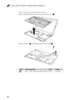
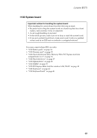
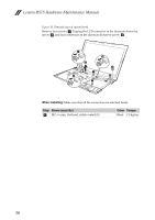
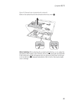
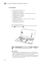
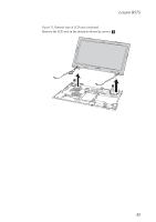
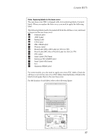
Lenovo B575 Hardware Maintenance Manual 1110 LCD unit For access, remove these FRUs in order: • "1010 Battery pack" on page 34 • "1020 Dummy card" on page 35 • "1030 Hard disk drive(HDD)/Memory/Mini PCI Express Card slot compartment cover" on page 36 • "1040 Hard disk drive" on page 37 • "1050 Optical drive" on page 38 • "1060 DIMM" on page 39 • "1070 PCI Express Mini Card for wireless LAN/WAN" on page 40 • "1080 Keyboard" on page 42 • "1090 Keyboard bezel" on page 45 • "1100 System board" on page 49 Figure 11. Removal steps of LCD unit Release the antenna cables from the cable guides in the direction shown by arrows a. Remove four screws b. 22 1 2 2 1 1 Step b Screw (quantity) Color M2.5 × 6 mm, flat-head, nylok-coated (4) White Torque 2.5 kgfcm When installing: • Route the antenna cables along the cable guides. As you route the cables, make sure that they are not subjected to any tension. Tension could cause the cables to be damaged by the cable guides, or a wire to be broken. • Make sure that the LCD connector is attached firmly and make sure that you do not pinch the antenna cables when you attach the LCD assembly. Route the LCD cable along the cable guides. 52
-
 1
1 -
2
-
3
-
4
-
5
-
6
-
7
-
8
-
9
-
10
-
11
-
12
-
13
-
14
-
15
-
16
-
17
-
18
-
19
-
20
-
21
-
22
-
23
-
24
-
25
-
26
-
27
-
28
-
29
-
30
-
31
-
32
-
33
-
34
-
35
-
36
-
37
-
38
-
39
-
40
-
41
-
42
-
43
-
44
-
45
-
46
-
47
-
48
-
49
-
50
-
 51
51 -
 52
52 -
 53
53 -
 54
54 -
 55
55 -
 56
56 -
 57
57 -
 58
58 -
 59
59 -
 60
60 -
 61
61 -
62
-
63
-
64
-
65
-
66
-
67
-
68
-
69
-
70
-
71
-
72
-
73
-
74
-
75
-
76
-
77
-
78
-
79
-
80
-
81
-
82
-
83
-
84
-
85
-
86
 |
 |