Lenovo Flex 2-14 Hardware Maintenance Manual - Lenovo Flex 2-14, 2-14D, 2-15, - Page 58
Flex 2-14/Flex 2-14 D, Flex 2-14D
 |
View all Lenovo Flex 2-14 manuals
Add to My Manuals
Save this manual to your list of manuals |
Page 58 highlights
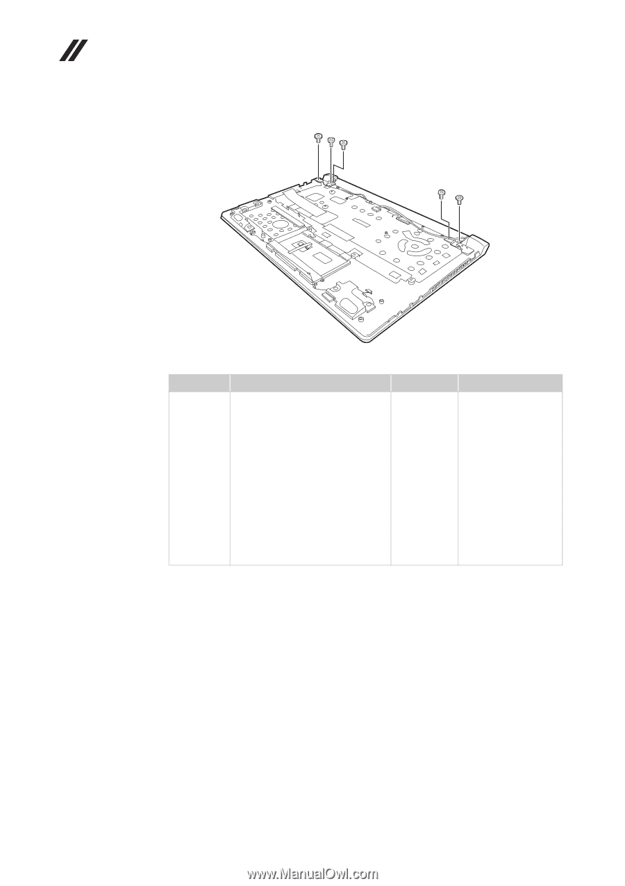
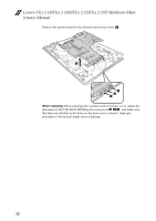
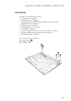
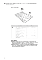
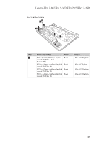
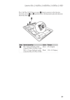
Lenovo Flex 2-14/Flex 2-14D/Flex 2-15/Flex 2-15D Hardware Maintenance Manual Flex 2-14/Flex 2-14 D: aaa aa Step a Screw (quantity) Color M2.5 × 4 mm, flat-head, nylok- Silver coated (5) (Flex 2-14/ Flex 2-14D) M2.5 × 4.5 mm, flat-head, nylok-coated (4) (Flex 2-15/ Flex 2-15D) Silver M2.5 × 4.5 mm, flat-head, nylok-coated (Flex 2-15/ Flex 2-15D) Silver M2.0 × 3.5 mm, flat-head, nylok-coated (Flex 2-15/ Flex 2-15D) Black Torque 18~2.0 kgfcm 3.0+/-0.3 kgfcm 3.0+/-0.3 kgfcm 1.85+/-0.15 kgfcm When installing: • Route the antenna cables along the cable guides. As you route the cables, make sure that they are not subjected to any tension. Tension could cause the cables to be damaged by the cable guides, or a wire to be broken. • Make sure that the LCD connector is attached firmly and make sure that you do not pinch the antenna cables when you attach the LCD assembly. Route the LCD cable along the cable guides. 54
-
 1
1 -
2
-
3
-
4
-
5
-
6
-
7
-
8
-
9
-
10
-
11
-
12
-
13
-
14
-
15
-
16
-
17
-
18
-
19
-
20
-
21
-
22
-
23
-
24
-
25
-
26
-
27
-
28
-
29
-
30
-
31
-
32
-
33
-
34
-
35
-
36
-
37
-
38
-
39
-
40
-
41
-
42
-
43
-
44
-
45
-
46
-
47
-
48
-
49
-
50
-
51
-
52
-
 53
53 -
 54
54 -
 55
55 -
 56
56 -
 57
57 -
 58
58 -
 59
59 -
 60
60 -
 61
61 -
 62
62 -
 63
63 -
64
-
65
-
66
-
67
-
68
-
69
-
70
-
71
-
72
-
73
-
74
-
75
-
76
-
77
-
78
-
79
-
80
-
81
-
82
-
83
-
84
-
85
-
86
-
87
-
88
-
89
-
90
-
91
-
92
-
93
-
94
-
95
-
96
-
97
-
98
-
99
-
100
-
101
-
102
-
103
-
104
-
105
-
106
-
107
-
108
-
109
 |
 |