Lenovo Flex 3 -1435 Laptop Hardware Maintenance Manual - Lenovo Flex 3-1470, F - Page 72
board cable in the direction shown by arrows, Remove the sensor board in the direction shown by arrow
 |
View all Lenovo Flex 3 -1435 Laptop manuals
Add to My Manuals
Save this manual to your list of manuals |
Page 72 highlights
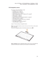
Flex 3-1470/Flex 3-1470 (HSW)/Flex 3-1435/Flex 3-1475/Flex 3-1570/ Flex 3-1570 (HSW)/Flex 3-1535 Hardware Maintenance Manual Figure 13. Removal steps of sensor board and antenna assembly (continued) Peel off the adhesive tape securing the antenna boards. Release the cables from the cable guide, and then remove the antenna assembly and sensor board cable in the direction shown by arrows 3. 3 3 3 Remove the sensor board in the direction shown by arrow 4. 4 68
-
 1
1 -
2
-
3
-
4
-
5
-
6
-
7
-
8
-
9
-
10
-
11
-
12
-
13
-
14
-
15
-
16
-
17
-
18
-
19
-
20
-
21
-
22
-
23
-
24
-
25
-
26
-
27
-
28
-
29
-
30
-
31
-
32
-
33
-
34
-
35
-
36
-
37
-
38
-
39
-
40
-
41
-
42
-
43
-
44
-
45
-
46
-
47
-
48
-
49
-
50
-
51
-
52
-
53
-
54
-
55
-
56
-
57
-
58
-
59
-
60
-
61
-
62
-
63
-
64
-
65
-
66
-
 67
67 -
 68
68 -
 69
69 -
 70
70 -
 71
71 -
 72
72 -
 73
73 -
 74
74 -
 75
75 -
 76
76 -
 77
77 -
78
-
79
-
80
-
81
-
82
-
83
-
84
-
85
-
86
-
87
-
88
-
89
-
90
-
91
-
92
-
93
-
94
-
95
-
96
-
97
-
98
 |
 |

68
Flex 3-1470/Flex 3-1470 (HSW)/Flex 3-1435/Flex 3-1475/Flex 3-1570/
Flex 3-1570 (HSW)/Flex 3-1535 Hardware Maintenance Manual
Figure 13. Removal steps of sensor board and antenna assembly (continued)
Peel off the adhesive tape securing the antenna boards. Release the cables
from the cable guide, and then remove the antenna assembly and sensor
board cable in the direction shown by arrows
3
.
3
3
3
Remove the sensor board in the direction shown by arrow
4
.
4