Lenovo Flex 3-1120 Laptop Hardware Maintenance Manual - Lenovo Flex 3-1120 - Page 58
LCD module, 1090 Power assembly
 |
View all Lenovo Flex 3-1120 Laptop manuals
Add to My Manuals
Save this manual to your list of manuals |
Page 58 highlights
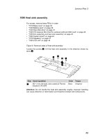
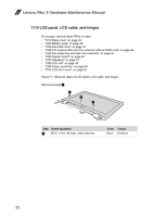
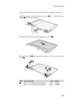
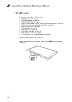
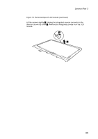
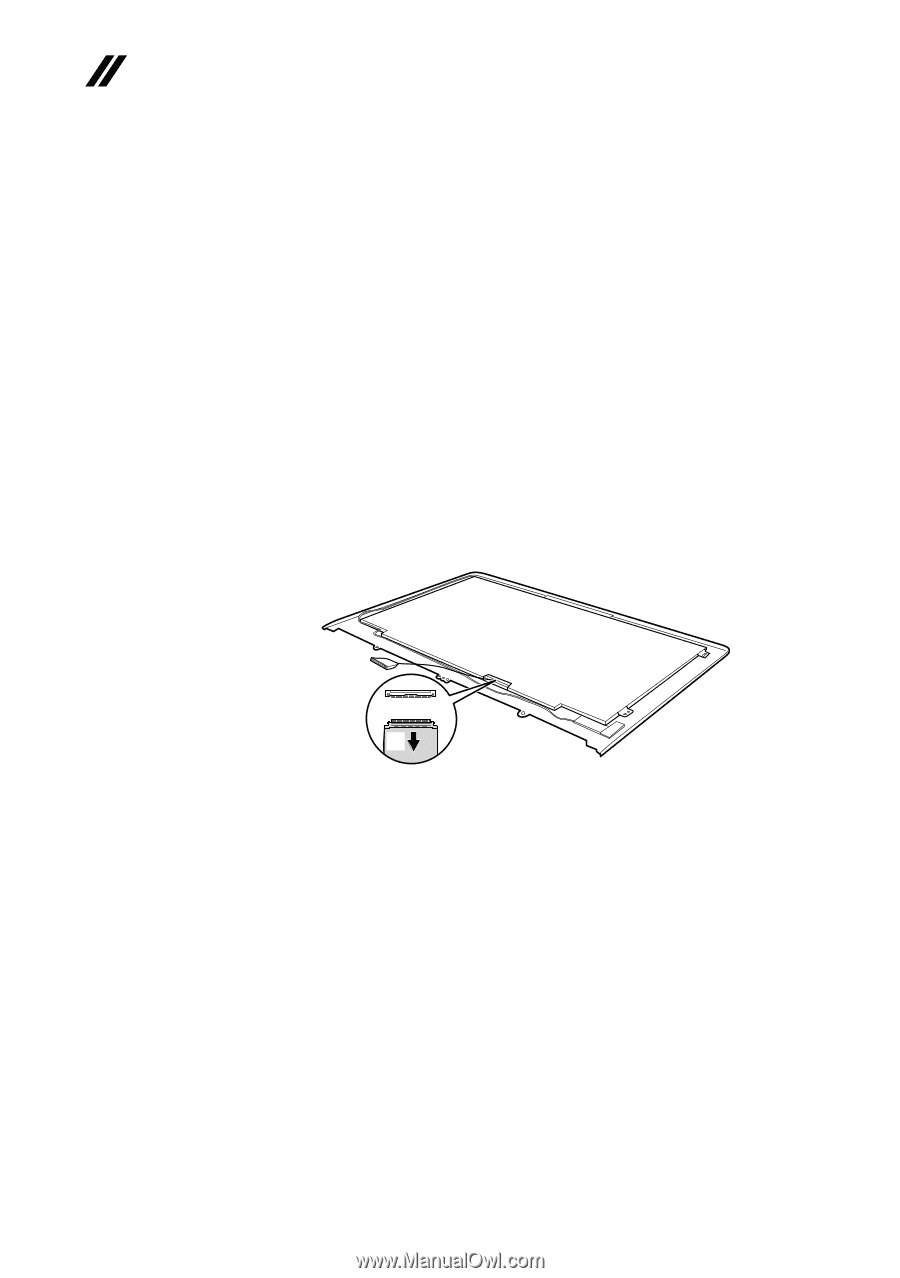
Lenovo Flex 3 Hardware Maintenance Manual 1120 LCD module For access, remove these FRUs in order: • "1010 Base cover" on page 34 • "1020 Battery pack" on page 36 • "1030 Hard disk drive" on page 37 • "1040 PCI Express Mini Card for wireless LAN and SSD card" on page 40 • "1050 Fan assembly and heat sink assembly" on page 42 • "1060 System board" on page 44 • "1070 Speakers" on page 47 • "1080 LCD unit" on page 48 • "1090 Power assembly" on page 49 • "1100 LCD front cover" on page 50 • "1110 Mic board, LCD cover, and hinges" on page 52 Figure 12. Removal steps of LCD module Detach the connector in the direction shown by arrow 1. Then remove the LCD cable. a 54
-
 1
1 -
2
-
3
-
4
-
5
-
6
-
7
-
8
-
9
-
10
-
11
-
12
-
13
-
14
-
15
-
16
-
17
-
18
-
19
-
20
-
21
-
22
-
23
-
24
-
25
-
26
-
27
-
28
-
29
-
30
-
31
-
32
-
33
-
34
-
35
-
36
-
37
-
38
-
39
-
40
-
41
-
42
-
43
-
44
-
45
-
46
-
47
-
48
-
49
-
50
-
51
-
52
-
 53
53 -
 54
54 -
 55
55 -
 56
56 -
 57
57 -
 58
58 -
 59
59 -
 60
60 -
 61
61 -
 62
62 -
 63
63 -
64
-
65
-
66
-
67
-
68
-
69
-
70
-
71
-
72
-
73
-
74
-
75
-
76
-
77
-
78
-
79
-
80
 |
 |
54
Lenovo Flex 3 Hardware Maintenance Manual
1120 LCD module
For access, remove these FRUs in order:
•
“1010 Base cover” on page 34
•
“1020 Battery pack” on page 36
•
“1030 Hard disk drive” on page 37
•
“1040 PCI Express Mini Card for wireless LAN and SSD card” on page 40
•
“1050 Fan assembly and heat sink assembly” on page 42
•
“1060 System board” on page 44
•
“1070 Speakers” on page 47
•
“1080 LCD unit” on page 48
•
“1090 Power assembly” on page 49
•
“1100 LCD front cover” on page 50
•
“1110 Mic board, LCD cover, and hinges” on page 52
Figure 12. Removal steps of LCD module
Detach the connector in the direction shown by arrow
1
. Then remove the
LCD cable.
a