Lenovo G40-80 Laptop Hardware Maintenance Manual - Lenovo G40-30, G40-45, G40- - Page 62
LCD unit
 |
View all Lenovo G40-80 Laptop manuals
Add to My Manuals
Save this manual to your list of manuals |
Page 62 highlights
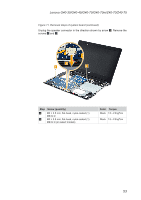
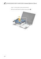
G40-30/G40-45/G40-70/G40-70m/Z40-70/Z40-75 Hardware Maintenance Manual 1140 LCD unit For access, remove these FRUs in order: • "1010 Battery pack" on page 33 • "1020 Base cover" on page 34 • "1030 Optical drive" on page 36 • "1040 Hard disk drive" on page 37 • "1050 PCI Express Mini Card for wireless LAN" on page 39 • "1070 Fan assembly" on page 42 • "1080 Keyboard" on page 44 • "1090 Keyboard bezel" on page 47 • "1100 USB&audio board" on page 50 • "1110 System board" on page 52 • "1130 Speakers and DC-in cable" on page 56 Figure 14. Removal steps of LCD unit Release the antenna cables from the cable guides and then remove the screws 1. 1 1 Step Screw (quantity) 1 M2 × 3.5 mm, flat-head, nylok-coated (4) LCD Module to D Color Torque Black 1.5 ~ 2.0 kgf*cm When installing: • Route the antenna cables along the cable guides. As you route the cables, make sure that they are not subjected to any tension. Tension could cause the cables to be damaged by the cable guides, or a wire to be broken. • Make sure that the LCD connector is attached firmly and that you do not pinch the antenna cables when you attach the LCD assembly. Route the LCD cable along the cable guides. 58
-
 1
1 -
2
-
3
-
4
-
5
-
6
-
7
-
8
-
9
-
10
-
11
-
12
-
13
-
14
-
15
-
16
-
17
-
18
-
19
-
20
-
21
-
22
-
23
-
24
-
25
-
26
-
27
-
28
-
29
-
30
-
31
-
32
-
33
-
34
-
35
-
36
-
37
-
38
-
39
-
40
-
41
-
42
-
43
-
44
-
45
-
46
-
47
-
48
-
49
-
50
-
51
-
52
-
53
-
54
-
55
-
56
-
 57
57 -
 58
58 -
 59
59 -
 60
60 -
 61
61 -
 62
62 -
 63
63 -
 64
64 -
 65
65 -
 66
66 -
 67
67 -
68
-
69
-
70
-
71
-
72
-
73
-
74
-
75
-
76
-
77
-
78
-
79
-
80
-
81
-
82
-
83
-
84
-
85
-
86
-
87
-
88
-
89
-
90
-
91
 |
 |
